Contents
Manual
Table of Contents
Section Product Description Introduction
Operation and Maintenance Manual
Major Components
Main Enclosure
Control Components
Section Product Description
Interconnection Standards Compliance
Power Control Unit PCU
Equipment Symbol
Section Product Description Specifications
Main Enclosure Door Interlock Switch
Section Safety Safety Features
Fault Reporting
PV Ground Fault Detection
Isolation Procedure
Section Safety
Over/Under Voltage and Frequency
Anti Island Protection
Utility Side Isolation Transformer Requirements
Torque and Wire Gauge Specifications
Installation Instructions
Section Installation and Initial TURN-ON
Installation
Cable Entry Area Array Grounding
Ground Fault Detection
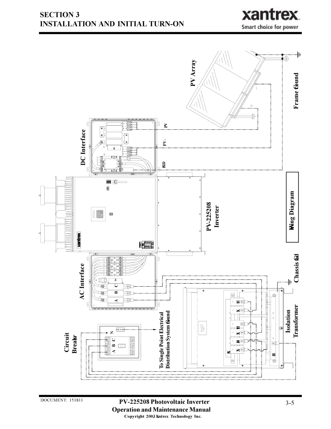
Interconnection Wiring
PV Array Frame Ground DC Interface
PV-225208 Inverter Wiring Diagram Chassis Gnd Transformer
Interface
Circuit Breaker
Initial Power
Visual Inspection, PV Array Wiring
Visual Inspection, Isolation Transformer WYE/WYE
Visual Inspection, PV-225208
System Verification
Power Tracker Fine Tuning
Overview
Section Operation Description of System Operation
Operating States
Fixed Unity Power Factor Operation
Operation Features
Utility Voltage/Frequency Fault Automatic Reset
Section Operation
Operator Interface
Peak Power Tracking
Current Imbalance Detection
DC Overvoltage Detection
Section Operation
Setting the Date and Time
Commanding Goal State Changes
Manual State Transitions
Changing Write Parameter Values
Automatic State Transitions
Sleeping → Power Tracking → Sleeping
TURN-ON Procedure
AUTO-RESTART Feature
Any State → Fault
Alarm and Fault Conditions
Section Troubleshooting General
Programming Mode S
Section Troubleshooting
PV Overvoltage S
Bad Memory S
PV Auxiliary Switch Open H
Door Interlock Switch Open H
AC Voltage Too Low S
AC Voltage Too High S
YY27/YY28 Line Over-Current Fault S
XX25/XX26 Line Gate Drive Fault S
DC Bus Voltage High H
PV Over-Current Fault S
Section Preventative Maintenance Periodic Maintenance
Section Preventative Maintenance
READ/WRITE Parameter Menu
Section Appendix Faults Codes
Read-Only Parameters
Inverter States
Section Appendix
ADC
Drawings List
Warranty and Certification
Xantrex PV Series Limited Warranty and Registration
Page
Page
Page
Page
Page
Fab, Enclosure, Upper, 2 Bay, PV225208
Page
Fab, Enclosure, DC Interface, PV225208
Page
TB5
Source Control Specification

![]()
![]()
![]()
![]()
![]()
![]()
![]()
![]()
![]()
![]()
![]()
![]()
![]()
![]() DNG VP- +VP
DNG VP- +VP![]()
![]()
![]()
![]()
![]()
![]()
![]()
![]()
![]()
![]()
![]()
![]()
![]()
![]()
![]()
![]()
![]()
![]()
![]()
![]()
![]()
![]()
![]()
![]()
![]()
![]()
![]()
![]()
![]()
![]()
![]()
![]()
![]()
![]()
![]()
![]()
![]()
![]()
![]()
![]()
![]()
![]()
![]()
![]()
![]()
![]()
![]()
![]()
![]()
