SECTION 7
APPENDIX
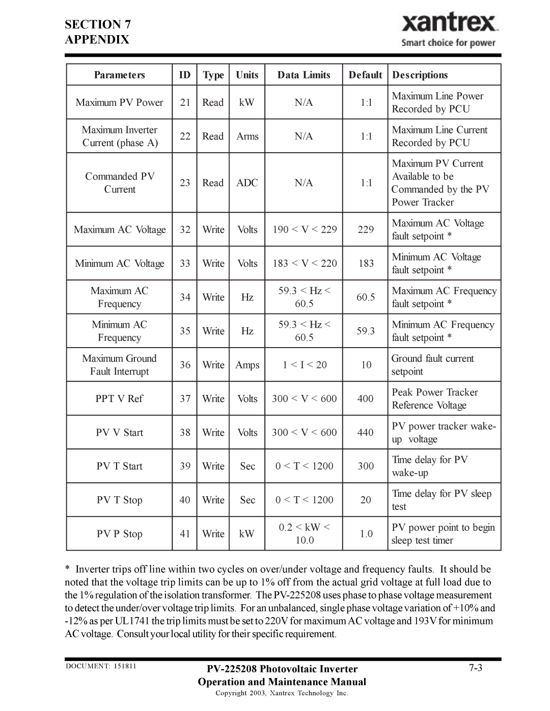
Parameters | ID | Type | Units | Data Limits | Default | Descriptions | |
|
|
|
|
|
|
| |
Maximum PV Power | 21 | Read | kW | N/A | 1:1 | Maximum Line Power | |
Recorded by PCU | |||||||
|
|
|
|
|
| ||
|
|
|
|
|
|
| |
Maximum Inverter | 22 | Read | Arms | N/A | 1:1 | Maximum Line Current | |
Current (phase A) | Recorded by PCU | ||||||
|
|
|
|
| |||
|
|
|
|
|
|
| |
|
|
|
|
|
| Maximum PV Current | |
Commanded PV | 23 | Read | ADC | N/A | 1:1 | Available to be | |
Current | Commanded by the PV | ||||||
|
|
|
|
| |||
|
|
|
|
|
| Power Tracker | |
|
|
|
|
|
|
| |
Maximum AC Voltage | 32 | Write | Volts | 190 < V < 229 | 229 | Maximum AC Voltage | |
fault setpoint * | |||||||
|
|
|
|
|
| ||
|
|
|
|
|
|
| |
Minimum AC Voltage | 33 | Write | Volts | 183 < V < 220 | 183 | Minimum AC Voltage | |
fault setpoint * | |||||||
|
|
|
|
|
| ||
|
|
|
|
|
|
| |
Maximum AC | 34 | Write | Hz | 59.3 < Hz < | 60.5 | Maximum AC Frequency | |
Frequency | 60.5 | fault setpoint * | |||||
|
|
|
| ||||
|
|
|
|
|
|
| |
Minimum AC | 35 | Write | Hz | 59.3 < Hz < | 59.3 | Minimum AC Frequency | |
Frequency | 60.5 | fault setpoint * | |||||
|
|
|
| ||||
|
|
|
|
|
|
| |
Maximum Ground | 36 | Write | Amps | 1 < I < 20 | 10 | Ground fault current | |
Fault Interrupt | setpoint | ||||||
|
|
|
|
| |||
|
|
|
|
|
|
| |
PPT V Ref | 37 | Write | Volts | 300 < V < 600 | 400 | Peak Power Tracker | |
Reference Voltage | |||||||
|
|
|
|
|
| ||
|
|
|
|
|
|
| |
PV V Start | 38 | Write | Volts | 300 < V < 600 | 440 | PV power tracker wake- | |
up voltage | |||||||
|
|
|
|
|
| ||
|
|
|
|
|
|
| |
PV T Start | 39 | Write | Sec | 0 < T < 1200 | 300 | Time delay for PV | |
|
|
|
|
|
| ||
|
|
|
|
|
|
| |
PV T Stop | 40 | Write | Sec | 0 < T < 1200 | 20 | Time delay for PV sleep | |
test | |||||||
|
|
|
|
|
| ||
|
|
|
|
|
|
| |
PV P Stop | 41 | Write | kW | 0.2 < kW < | 1.0 | PV power point to begin | |
10.0 | sleep test timer | ||||||
|
|
|
|
| |||
|
|
|
|
|
|
|
*Inverter trips off line within two cycles on over/under voltage and frequency faults. It should be noted that the voltage trip limits can be up to 1% off from the actual grid voltage at full load due to the 1% regulation of the isolation transformer. The
DOCUMENT: 151811 | ||
| Operation and Maintenance Manual |
|
Copyright 2003, Xantrex Technology Inc.
