TM500A specifications
Xantrex Technology is renowned for its innovative power solutions, and the TM500A is a standout model in its extensive product lineup. This advanced power inverter is engineered to meet the needs of both industrial applications and residential systems, providing users with reliable and efficient power conversion.One of the main features of the TM500A is its advanced inverter technology, which allows for high efficiency and performance. With an efficiency rating often exceeding 90%, the TM500A minimizes energy loss during the conversion process. This makes it an ideal choice for renewable energy systems, such as solar and wind, by maximizing the amount of usable power delivered to connected devices. The inverter is capable of converting DC power into high-quality AC power, suitable for a wide range of appliances and electronics.
The TM500A is designed with versatility in mind. It supports various input voltage systems, allowing it to be used in a multitude of setups. This flexibility is further enhanced by its ability to operate in both grid-tied and off-grid configurations, opening up possibilities for diverse applications. Whether in a residential setting powering home appliances or in industrial applications supporting heavy machinery, the TM500A adapts to customer needs.
Another characteristic that sets the TM500A apart is its robust safety features. This inverter is equipped with multiple layers of protection, including overload, short circuit, and over-temperature safeguards. These safety measures ensure that both the device and the connected load are protected from potential damage, providing peace of mind to users.
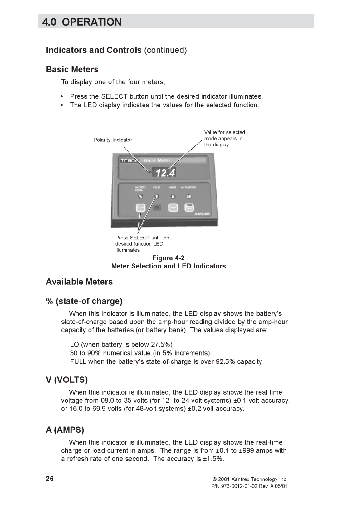
The TM500A also boasts user-friendly interfaces, including LED indicators and diagnostic features that make monitoring performance straightforward. This ease of use is complemented by a compact and lightweight design, making installation and integration into existing systems straightforward.
Finally, Xantrex's commitment to quality is evident in the TM500A's construction, which utilizes durable materials suitable for demanding environments. Overall, the Xantrex TM500A stands as a reliable, efficient, and versatile power conversion solution that meets the evolving demands of users across various sectors. Its combination of advanced technology, safety, and user-centric design makes it a top choice for anyone needing dependable power solutions.

