Using ChipScope with OPB IIC
R
The waveform viewer is more readable when buses rather than discrete signals are displayed. The Reverse Bus Order operation below Add to Bus in the figure can be useful in analyzing ChipScope results.
X979_24_022307
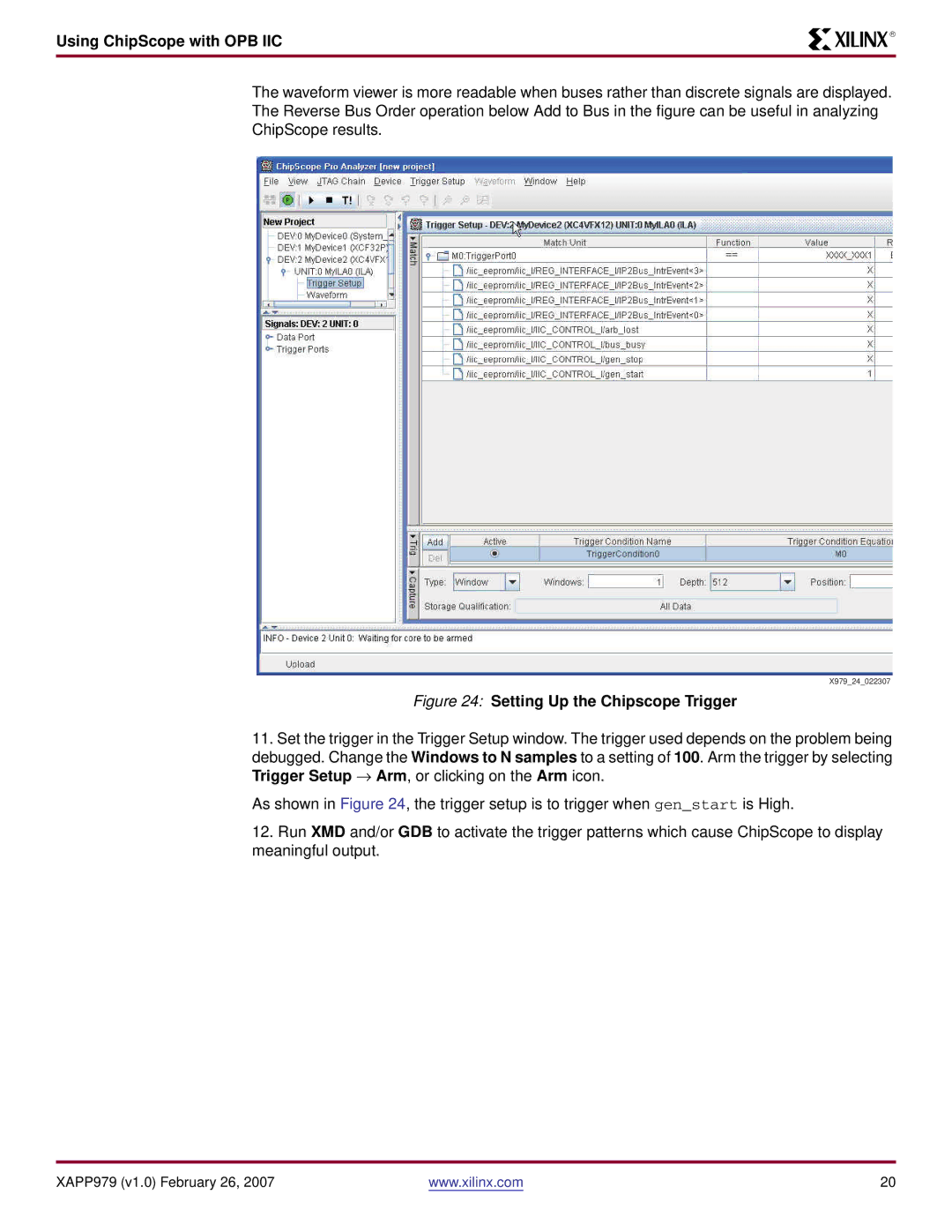
Figure 24: Setting Up the Chipscope Trigger
11.Set the trigger in the Trigger Setup window. The trigger used depends on the problem being
debugged. Change the Windows to N samples to a setting of 100. Arm the trigger by selecting Trigger Setup → Arm, or clicking on the Arm icon.
As shown in Figure 24, the trigger setup is to trigger when gen_start is High.
12.Run XMD and/or GDB to activate the trigger patterns which cause ChipScope to display meaningful output.
XAPP979 (v1.0) February 26, 2007 | www.xilinx.com | 20 |