Manuals
/
Brands
/
Computer Equipment
/
Switch
/
Xilinx
/
Computer Equipment
/
Switch
Xilinx
ML403
- page 31
1
31
33
33
Download
33 pages, 2.96 Mb
Simulation
XAPP979 (v1.0) February 26, 2007
www.xilinx.com
31
R
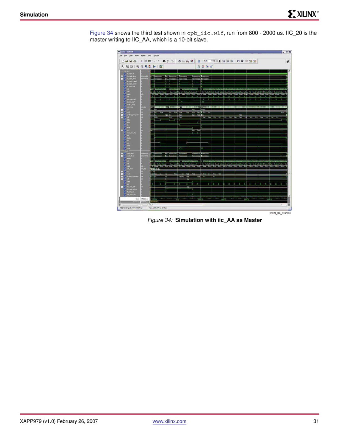
Figure 34
shows the third test shown in
opb_iic.wlf
, run from 800 - 2000 us. IIC_20 is the
master writing to IIC_AA, which is a 10-bit slave.
Figure 34:
Simulation with iic_AA as Master
X979_
3
4_012907
Contents
Main
Summary
Included Systems
Required Hardware/Tools
Reference System: OPB IIC Using the ML403 Evaluation Platform
Introduction
IIC Primer
Page
Reference System Specics
ML403 XC4VFX12 Address Map
Tab le 3 provides a description of the OPB IIC control register.
OPB IIC Registers
Tab le 2 provides the register map for the OPB IIC core.
Table 1: ML403 XC4VSX12 System Address Map
Page
Page
Conguring the OPB IIC Core
Microchip 24LC04
ML403 Board Information
Page
ML403 Board Information
Figure 13: Expansion Header
TotalPhase Aardvark Adapter
Interfacing to the OPB IIC on the ML403 Board to the Aardvark Adapter
Executing the Reference System using the Pre-Built Bitstream and the Compiled Software Applications
Executing the Reference System from EDK
Verifying the Reference Design with Xilinx Microprocessor Debugger
Software Projects
Projects interfacing to Microchip 24LC04
Projects interfacing to Aardvark Adapter
Running the Applications
Page
Page
Page
Page
Linux Kernel
Page
Page
Simulation
In most cases, after data is transmitted, the test waits for an interrupt from the OPB IIC.
Internal signal names used in the OPB IIC core are provided in Tab le 6.
Figure 28: OPB IIC Simulation Table 6: Internal Signals in OPB IIC
Page
Page
Page
Page
XAPP979 (v1.0) February 26, 2007 www.xilinx.com 30
Figure 33: Test code with iic_AA as Master
Page
Figure 35 provides the test code for simulation with IIC_AA as master.
Figure 35: Test Code for Simulation with iic_20 as Master