Reference System Specifics
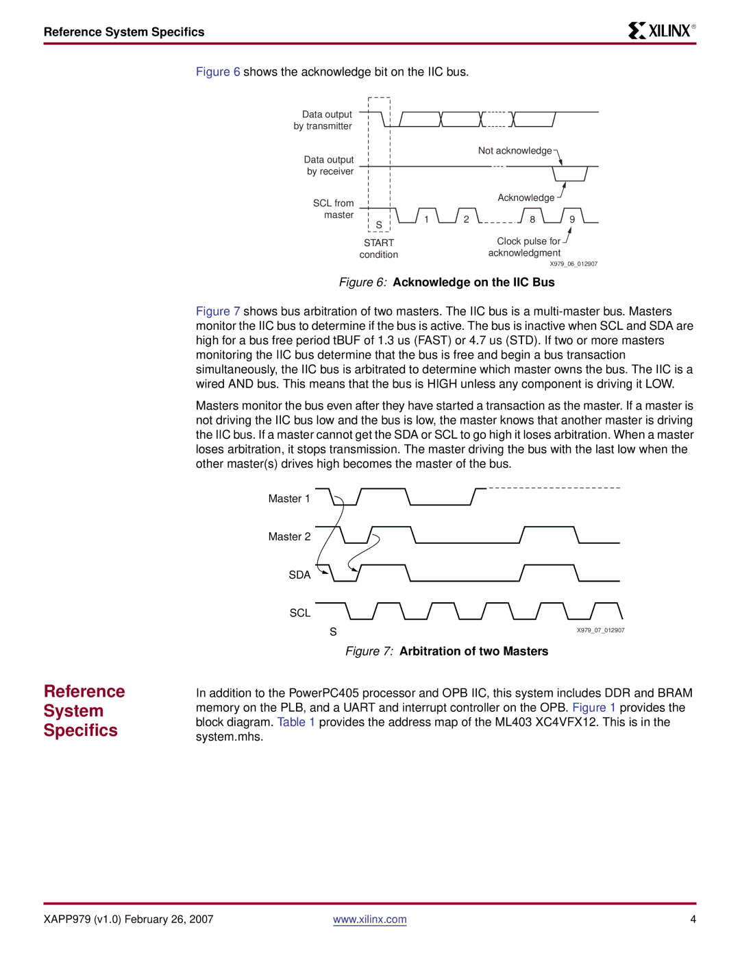
Figure 6 shows the acknowledge bit on the IIC bus.
Data output |
|
|
|
|
|
by transmitter |
|
|
|
|
|
Data output |
|
|
| Not acknowledge |
|
|
|
|
|
| |
by receiver |
|
|
|
|
|
SCL from |
|
|
| Acknowledge |
|
|
|
|
|
| |
master | S | 1 | 2 | 8 | 9 |
| |||||
|
|
|
|
| |
| START |
|
| Clock pulse for |
|
| condition |
|
| acknowledgment |
|
X979_06_012907
Figure 6: Acknowledge on the IIC Bus
R
Reference
System
Specifics
Figure 7 shows bus arbitration of two masters. The IIC bus is a multi-master bus. Masters monitor the IIC bus to determine if the bus is active. The bus is inactive when SCL and SDA are high for a bus free period tBUF of 1.3 us (FAST) or 4.7 us (STD). If two or more masters monitoring the IIC bus determine that the bus is free and begin a bus transaction simultaneously, the IIC bus is arbitrated to determine which master owns the bus. The IIC is a wired AND bus. This means that the bus is HIGH unless any component is driving it LOW.
Masters monitor the bus even after they have started a transaction as the master. If a master is not driving the IIC bus low and the bus is low, the master knows that another master is driving the IIC bus. If a master cannot get the SDA or SCL to go high it loses arbitration. When a master loses arbitration, it stops transmission. The master driving the bus with the last low when the other master(s) drives high becomes the master of the bus.
Master 1
Master 2
SDA
SCL
S | X979_07_012907 |
|
Figure 7: Arbitration of two Masters
In addition to the PowerPC405 processor and OPB IIC, this system includes DDR and BRAM memory on the PLB, and a UART and interrupt controller on the OPB. Figure 1 provides the block diagram. Table 1 provides the address map of the ML403 XC4VFX12. This is in the system.mhs.
XAPP979 (v1.0) February 26, 2007 | www.xilinx.com | 4 |
