Reference System Specifics
Table 3: OPB IIC Control Register (Contd)
R
Bit(s) | Name | Description | |
|
|
| |
|
| Transmit Acknowledge Enable. This bit specifies the value driven onto the SDA | |
|
| line during acknowledge cycles for both Master and Slave receivers. | |
27 | TXAK | Because Master receivers indicate the end of data reception by not | |
acknowledging the last byte of the transfer, this bit is used to end a Master | |||
|
| ||
|
| receiver transfer. As a slave, this bit must be set prior to receiving the byte to no | |
|
| acknowledge. | |
|
|
| |
|
| Transmit/Receive Mode Select. This bit selects the direction of Master/Slave | |
28 | TX | transfers. This bit does not control the Read/Write bit that is sent on the bus with | |
the address. The Read/Write bit that is sent with an address must be the LSB of | |||
|
| ||
|
| the address written into the transmit FIFO. | |
|
|
| |
|
| Master/Slave Mode Select. When this bit is changed from 0 to 1, the OPB IIC | |
|
| Bus Interface generates a START condition in Master mode. When this bit is | |
29 | MSMS | cleared, a STOP condition is generated and the OPB IIC Bus Interface switches | |
|
| to Slave mode. When this bit is cleared by the hardware, because arbitration for | |
|
| the bus has been lost, a STOP condition is not generated. | |
|
|
| |
30 | Tx FIFO | Transmit FIFO Reset. This bit must be set if arbitration is lost or if a transmit error | |
Reset | occurs to flush the FIFO. | ||
| |||
|
|
| |
31 | EN | OPB IIC Enable. This bit must be set before any other CR bits have any effect. | |
|
|
|
Status Register (SR)
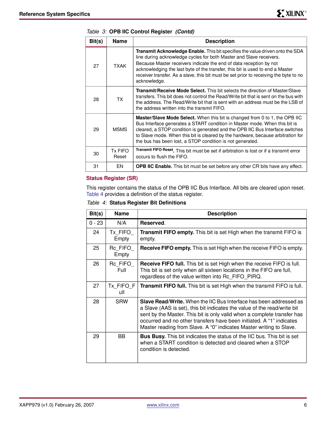
This register contains the status of the OPB IIC Bus Interface. All bits are cleared upon reset. Table 4 provides a definition of the status register.
Table 4: Status Register Bit Definitions
Bit(s) | Name | Description |
|
|
|
0 - 23 | N/A | Reserved. |
|
|
|
24 | Tx_FIFO_ | Transmit FIFO empty. This bit is set High when the transmit FIFO is |
| Empty | empty. |
|
|
|
25 | Rc_FIFO_ | Receive FIFO empty. This is set High when the receive FIFO is empty. |
| Empty |
|
|
|
|
26 | Rc_FIFO_ | Receive FIFO full. This bit is set High when the receive FIFO is full. |
| Full | This bit is set only when all sixteen locations in the FIFO are full, |
|
| regardless of the value written into Rc_FIFO_PIRQ. |
|
|
|
27 | Tx_FIFO_F | Transmit FIFO full. This bit is set High when the transmit FIFO is full. |
| ull |
|
|
|
|
28 | SRW | Slave Read/Write. When the IIC Bus Interface has been addressed as |
|
| a Slave (AAS is set), this bit indicates the value of the read/write bit |
|
| sent by the Master. This bit is only valid when a complete transfer has |
|
| occurred and no other transfers have been initiated. A “1” indicates |
|
| Master reading from Slave. A “0” indicates Master writing to Slave. |
|
|
|
29 | BB | Bus Busy. This bit indicates the status of the IIC bus. This bit is set |
|
| when a START condition is detected and cleared when a STOP |
|
| condition is detected. |
|
|
|
XAPP979 (v1.0) February 26, 2007 | www.xilinx.com | 6 |
