Eaton Electrical 10640205, APR48 quick start

Page 17
Ensure that the polarity at the dc outlet(s) matches the power input polarity of your equipment. Connecting reverse polarity equipment power cables to the dc outlets of an APS dc power system might cause damage to your equipment. Such damage is not covered by our warranty.
Ensure that the correct cable sizes have bee used (18AWG for 6A outlets and 12AWG for 25A outlets).
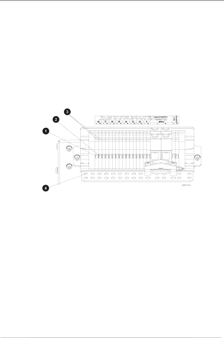
4 To ensure reliable connections at the terminal blocks of the dc outlets, torque the clamp screws 0.4 – 0.6Nm (3.5 – 5.3 lb-in).
5 Use cable-ties (not supplied) and the provided cable-tie holes on the cable support bracket to tie down the load cables.
APS3-06X (Desktop Versions) Before proceeding check you have:
Terminate the positive load cable(s) at the (+) terminal block(s) of the dc outlet(s).
Terminate the negative load cable(s) at the (-) terminal block(s) of the dc outlet(s).
1 Strip approximately 10mm (”) of the insulation from the cable ends.
2
3
Data Power Solutions Quick Start Guide
APS3-05X and APS6-05X(Rack-Mounted Versions)

4 x load cable clamps

8 x 25mm blunt ended screws

8 x 5mm and 4 x 10mm cable sleeves (50mm long) Depending on the cable sizes, not all sleeves will be required.

1mm2 (18 AWG) cable for connection to 6A outlets.

4mm2 (12 AWG) cable for connection to 25A outlets.

Copyright © 2006-2009 Eaton Corporation. All Rights Reserved.

17

10640205 February 2009


Image 17
Contents Data Power Solutions Quick Start Guide Data Power Solutions Quick Start Guide Contents For Further Information and Technical Assistance Worldwide SupportAccess Power Rectifiers APS3 and APS6 Series 48V DC Power SystemsGeneral Description SM45 Supervisory ModuleInputs Pre-InstallationLow Voltage Disconnect if applicable Data Power Solutions Quick Start Guide Wechselspannungs-Eingänge Entrées Alimentation SecteurOutputs Equipment ClassificationIngressi C.A Entradas CARectifiers Batteries if applicableGleichrichter RedresseursRaddrizzatori RectificadoresEntretien Location and EnvironmentServicing Wartung EMC ComplianceManutenzione ReparacionesMounting the APS DC Power System Location and Environment InstallationInspecting the Equipment and Reporting Damage Important Notes for Rack Mounted SystemsWichtige Hinweise für Anlagen mit Schrankmontage Remarques importantes pour les systèmes montés dans un rackClearance Requirements Connecting the DC Load CablesDC Load Cable Specifications Page Strip cable ends Fit load cable clampsFit cable and sleeves Terminate cablesBattery Sizing Installing the External Batteries if applicableBattery Location Arrange sleeves and tighten clamp screwsBattery Fault Protection Batterieschutz Protection en cas de défaut de la batterieBefore You Start Battery Cable SpecificationsPrepare cable clamp Strip cable and fit sleeveRepeat for other battery cables if required Arrange sleeve and clamp the battery cablesTerminate cable Remove knockout and fit coverMounting the Battery Temperature Sensor Connecting the Battery Temperature Sensor CableConnecting the APS DC Power System to the AC Supply AC Supply RequirementsInserting the Access Power Rectifiers AC InstallationPre-Power-Up Check CommissioningApplying DC Power to the Load Applying AC PowerConfiguring the APS DC Power System for Operation Battery Input Circuit Breakers Output Circuit Breaker Field Replacement and RepairUL Listed Mark Desktop variants APS3-060 & APS3-061System Input SpecificationsSystem Output EnvironmentRectifiers Dimensions H, W, DWeight