Mitsubishi Electronics WS-55859, WS-73909, WS-65909, WS-65869, WS-55909 Back Panel Functions

Page 13

Part II: Installation

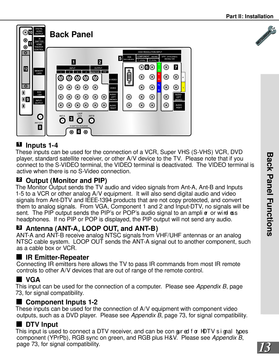
10 Back Panel

11

1

2

12


9


3


8

4


5


6

7

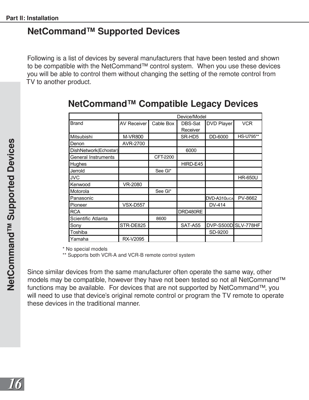
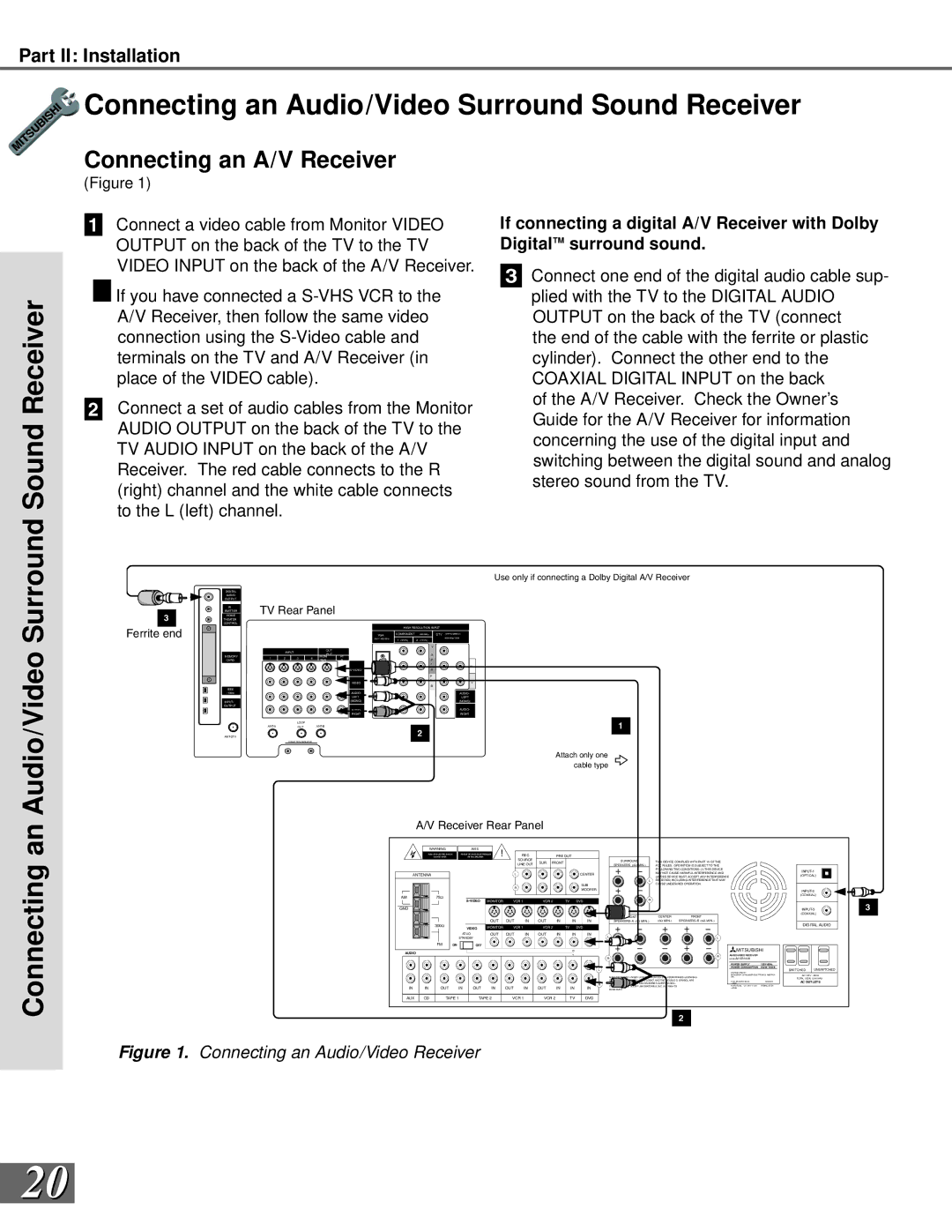
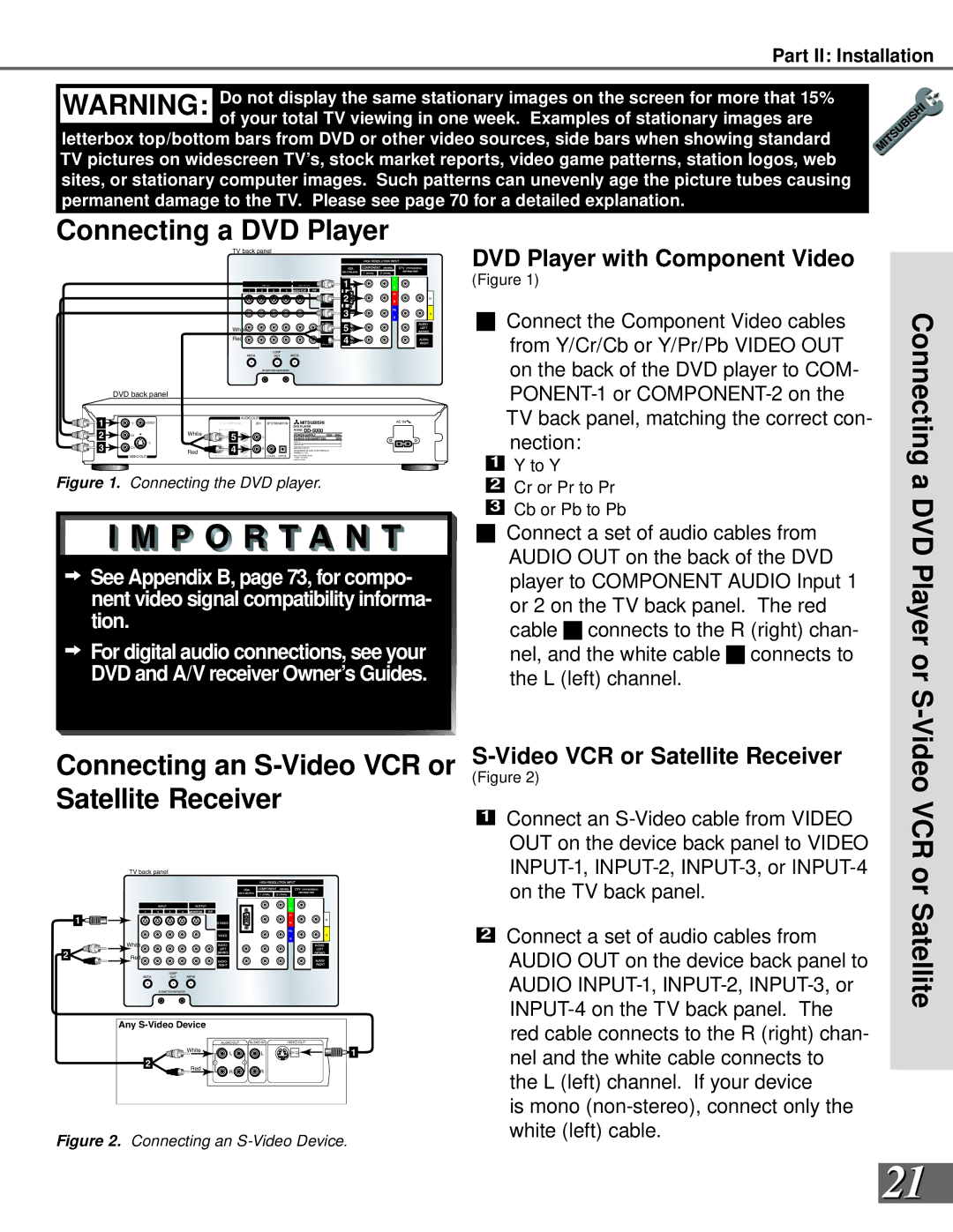
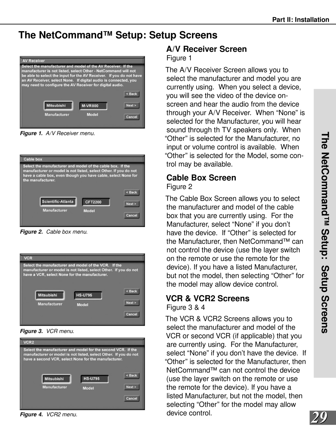
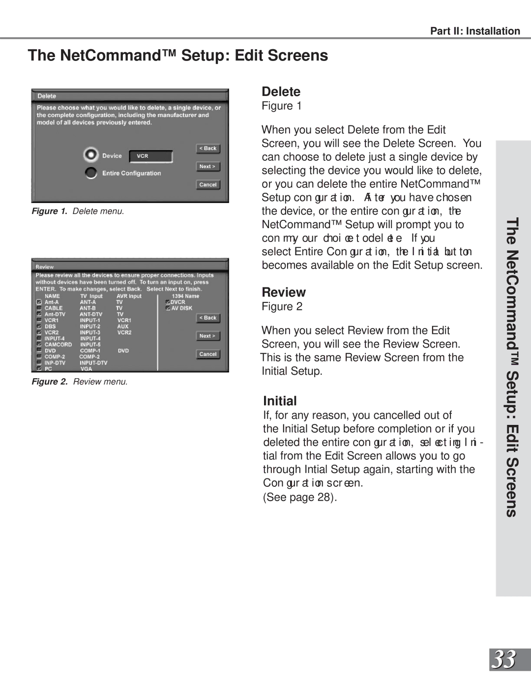
1Inputs 1-4

These inputs can be used for the connection of a VCR, Super VHS (S-VHS) VCR, DVD player, standard satellite receiver, or other A/V device to the TV. Please note that if you connect to the S-VIDEO terminal, the VIDEO terminal is deactivated. The VIDEO terminal is active when there is no S-Video connection.

2Output (Monitor and PIP)

The Monitor Output sends the TV audio and video signals from Ant-A, Ant-B and Inputs 1-5 to a VCR or other analog A/V equipment. It will also send digital audio and video signals from Ant-DTV and IEEE-1394 products that are not copy protected, and convert them to analog signals. From VGA, Component 1 and 2 and Input-DTV, no signals will be sent. The PIP output sends the PIP’s or POP’s audio signal to an ampli er or wirel ess headphones. If no PIP or POP is displayed, the PIP output will not send any audio.

3Antenna (ANT-A, LOOP OUT, and ANT-B)

ANT-A and ANT-B receive analog NTSC signals from VHF/UHF antennas or an analog NTSC cable system. LOOP OUT sends the ANT-A signal out to another component, such as a cable box or VCR.

4IR Emitter-Repeater

Back Panel Functions

Connecting IR emitters here allows the TV to pass IR commands from most IR remote controls to other A/V devices that are out of range of the remote control.

5

VGA

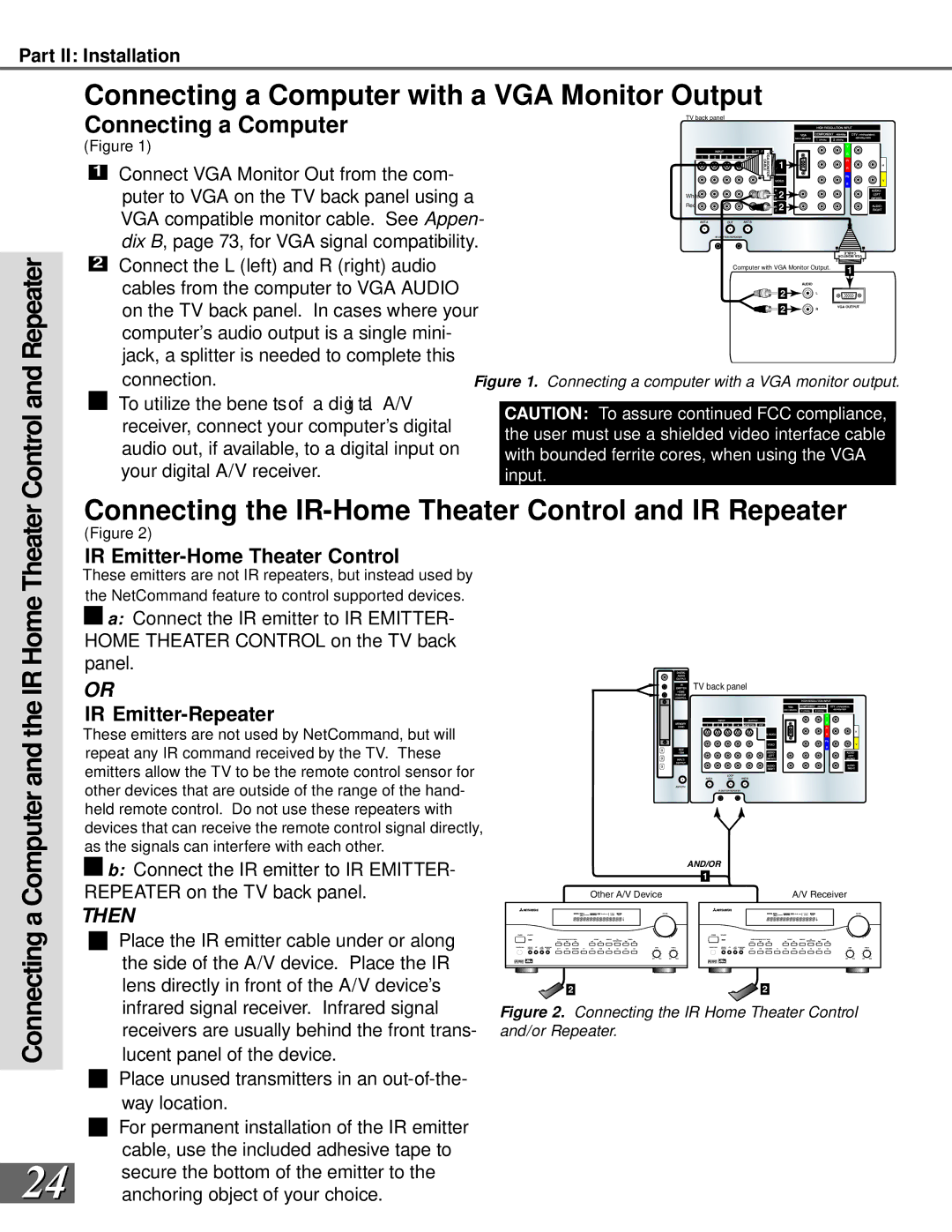
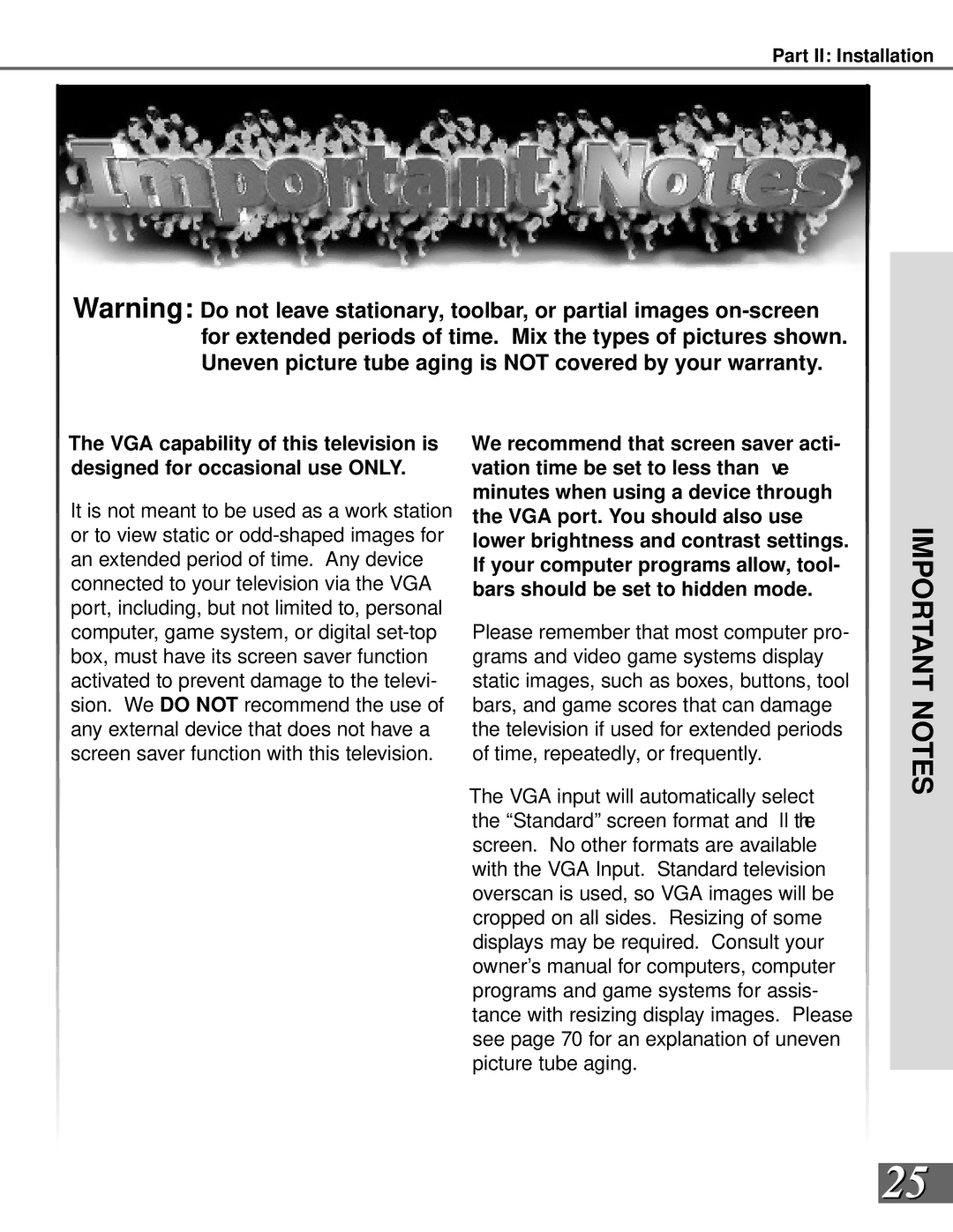
This input can be used for the connection of a computer. Please see Appendix B, page 73, for signal compatibility.

6

Component Inputs 1-2

These inputs can be used for the connection of A/V equipment with component video outputs, such as a DVD player. Please see Appendix B, page 73, for signal compatibility.

7

DTV Input

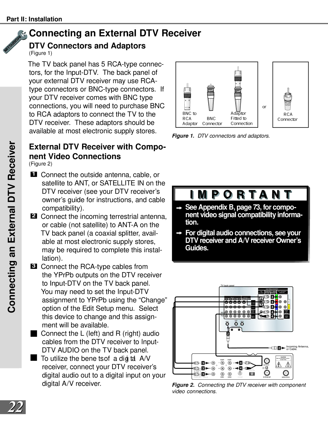
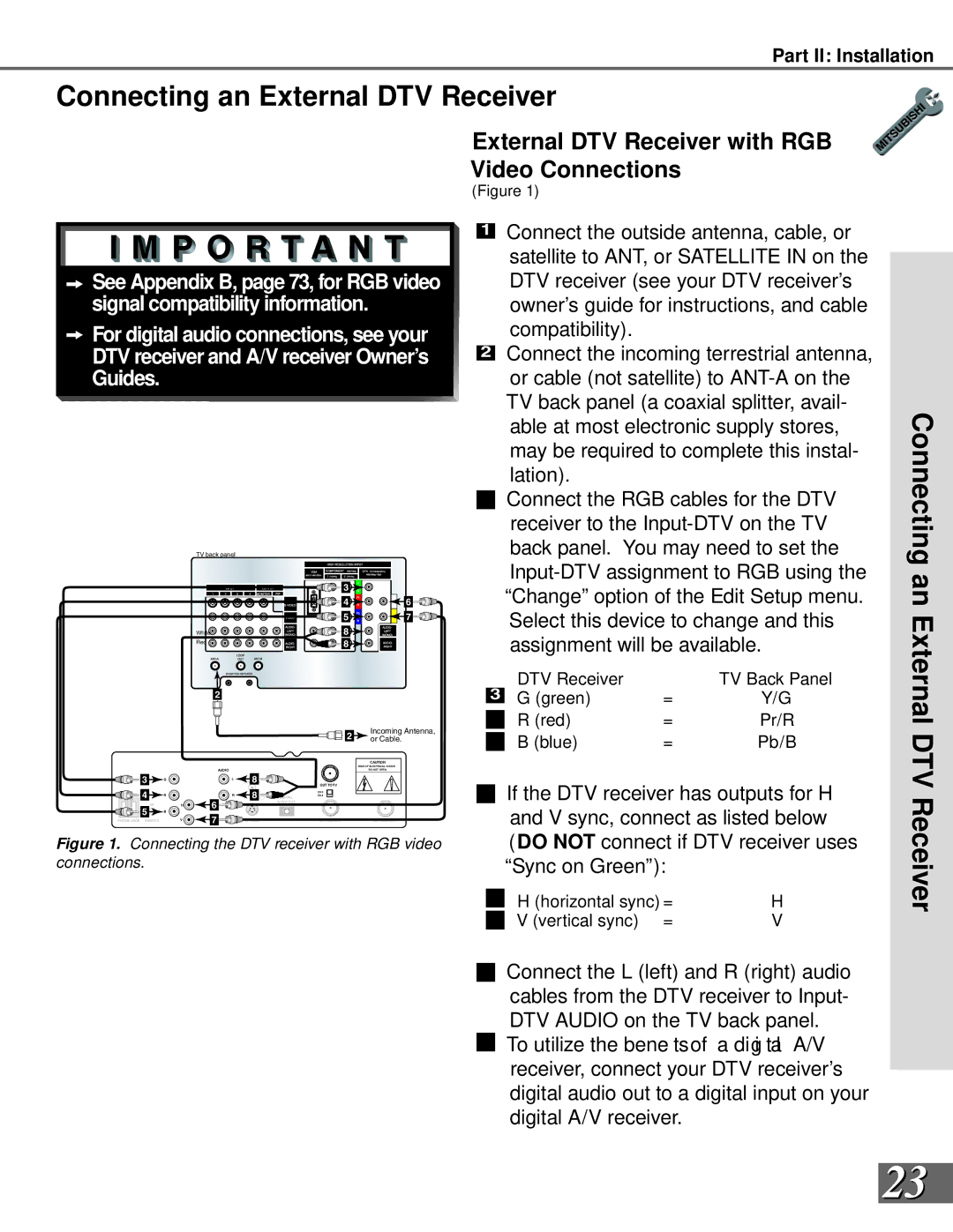
This input is used to connect a DTV receiver, and can be con gur ed f or HDTV s i gnal types


component (YPrPb), RGB sync on green, and RGB plus H&V. Please see Appendix B,

13

page 73, for signal compatibility.


Image 13
Contents W. m i t s u b i s h i t v. c o m Risk of Electric Shock Do not Open Table of Contents Important Safeguards Important SafeguardsSafeguards Important SafeguardsMDEAservice@bigscreen . mea . com Thank You We at Mitsubishi Would Like to Thank You Unpacking Your New TV Special FeaturesYour Page Installation Timer System ResetReset Front Control Panel Front Control Panel FunctionsBack Panel Functions Back PanelBack Panel Back Panel Functions Installation Con gur at ions & Ne t Co mma ndS e t up NetCommand Compatible Legacy Devices NetCommand Supported DevicesConnect the incoming cable to ANT-DTV on the TV back panel Antenna or Wall Outlet Cable for Digital BroadcastsCable Box Connecting an Analog Antenna, Cable, orSeparate UHF and VHF Antennas Antenna or Wall Outlet Cable for Analog BroadcastsAnalog Antennas or Wall Outlet Cable Connecting an Analog VCRAdding Composite Video or Video with Audio Connections Connecting an A/V Receiver Connecting an Audio/Video Surround Sound ReceiverSurround Sound Receiver Satellite Connecting a DVD PlayerDVD Player with Component Video Video VCR or Satellite ReceiverDTV Connectors and Adaptors Connecting an External DTV ReceiverExternal DTV Receiver with Compo- nent Video Connections Receiver Connecting an ExternalExternal DTV Receiver with RGB Video Connections Connecting the IR-Home Theater Control and IR Repeater Connecting a Computer with a VGA Monitor OutputConnecting a Computer Important Notes Cancel Button Initial SetupButtons Back ButtonThis page has been intentionally left blank Language Screen NetCommand Setup Setup ScreensCon gur at ion Sc r een Cable Box Screen Receiver ScreenVCR & VCR2 Screens DVD Screen DBS ScreenCamcorder Screen Finish Screen Review ScreenEdit Setup Screen NetCommand Setup Edit Setup ScreensAdd ChangeDelete NetCommand Setup Edit ScreensReview InitialNetCommand Setup Edit Screens NetCommand Setup Edit ScreensName ConnectionAVR to VCR Connection Monitor Out to AVR or VCRInput-DTV Connection Page Setup Menu System 3D Graphical Menu SystemDevice Selection Menu Selecting Device for PIP PIP Selection MenuMenu Screens Overview Setup MenuAntenna Menu Clock MenuCaptions Menu Timer MenuChip Lock Menu Audio/Video MenuSetup and Icon Position Setup Menu Edit Setup and Icon PositionEdit Setup Button EditReset Factory Defaults Convergence Setup Menu ConvergenceConvergence Convergence ScreenAdvanced Convergence Advanced Convergence, Transport, and LanguageTransport Menu LanguageMemorize Channels AntennaMemory Super Quick View SQV Antenna Menu Super Quick View SQVSQV Super Quick View Manual Clock Setting Clock Menu Auto or Manual Clock SettingAuto or Closed Captions Captions Menu Closed CaptionsClosed Captions CC BackgroundLock Chip Lock Menu PasscodeChip Chip Lock Menu V-Chip Chip Signal InformationChip Lock Front Button Lock Lock By TimeSetting The Timer Timer Menu Setting The TimerTimer On/Off DeviceAudio/Video Settings Menu TV Speakers Settings Menu TV SpeakersTV Speakers Audio Settings Setting Descriptions AudioVideo Settings Setting Descriptions VideoPage Operation Overview Remote Control Functions OverviewOperation Remote Control Functions Care and OperationSleep Timer, Operation of PIP and POP Remote Control Functions Channel Selection and Sleep TimerRemote Control Functions Operation of PIP and POP Channel Selection Sleep TimerOperation of PIP and POP Display Formats Remote Control Functions Display Formats To Program the Remote to Control NetCommand A/V Products Programming the Remote Control to Control Non-NetCommand Programming the Remote Control To Control Non-NetCommandSpecial Functions Remote Control Functions Special FunctionsOther stationary or repetitive computer style images Bypassing Front Button Lock Bypassing the V-Chip LockThis page has been intentionally left blank Component-1 and Component-2 Inputs Input Levels and Timing When Used With RGB Video SignalsVGA Input Input Connection CompatibilityReceivers Appendix C Remote Control Programming CodesDVD Players Satellite ReceiversAppendix D Cleaning and Service CleaningService Diamond Shield Installation WS-55909, and, WS-73909 Appendix E Diamond Shield InstallationAppendix F Cabinet Separation for Model WS-65869 For Appendix G Troubleshooting Problem Possible SolutionTV will not turn on after being plugged Appendix G Troubleshooting Problem Possible SolutionIndex Stationary Picture Index S-WMitsubishi Projection TV Limited Warranty Mitsubishi Projection TV Limited WarrantyPage Page Mitsubishi Digital Electronics America, Inc 871D330B10