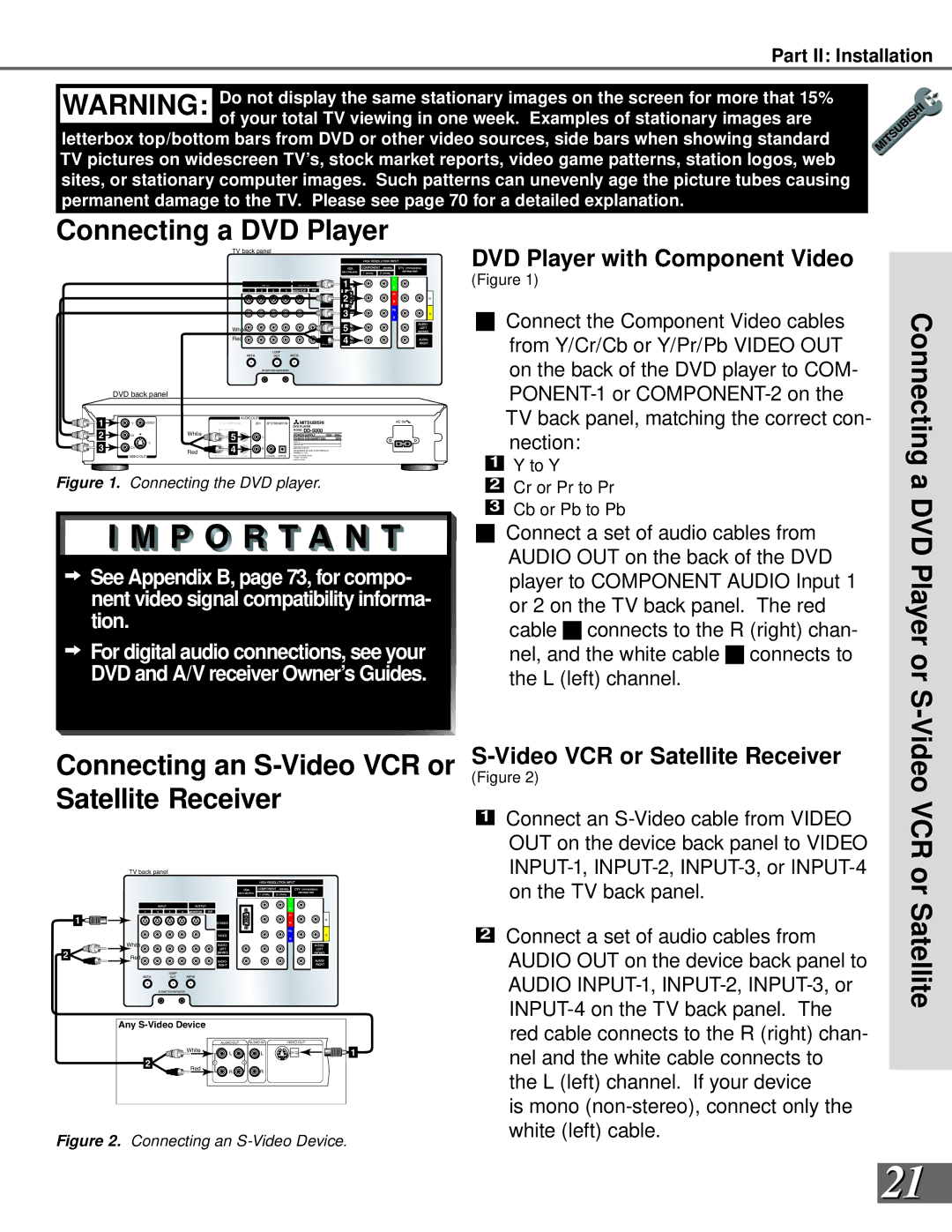
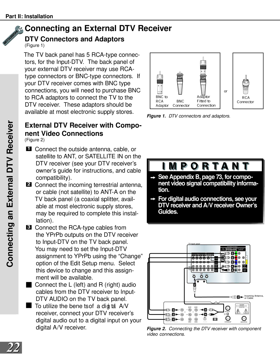
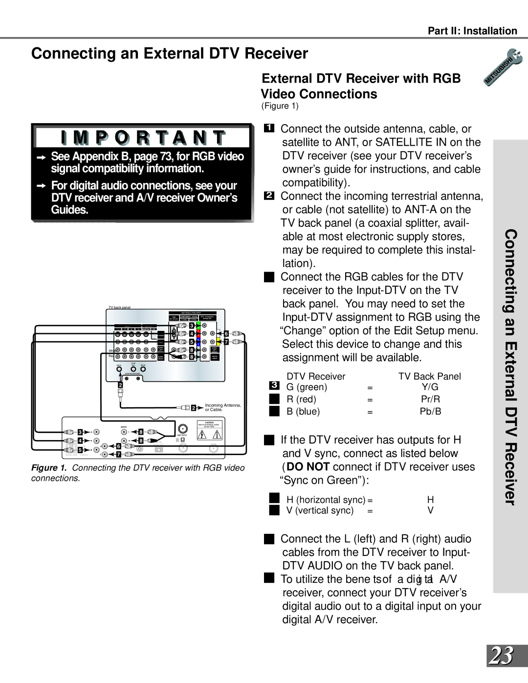
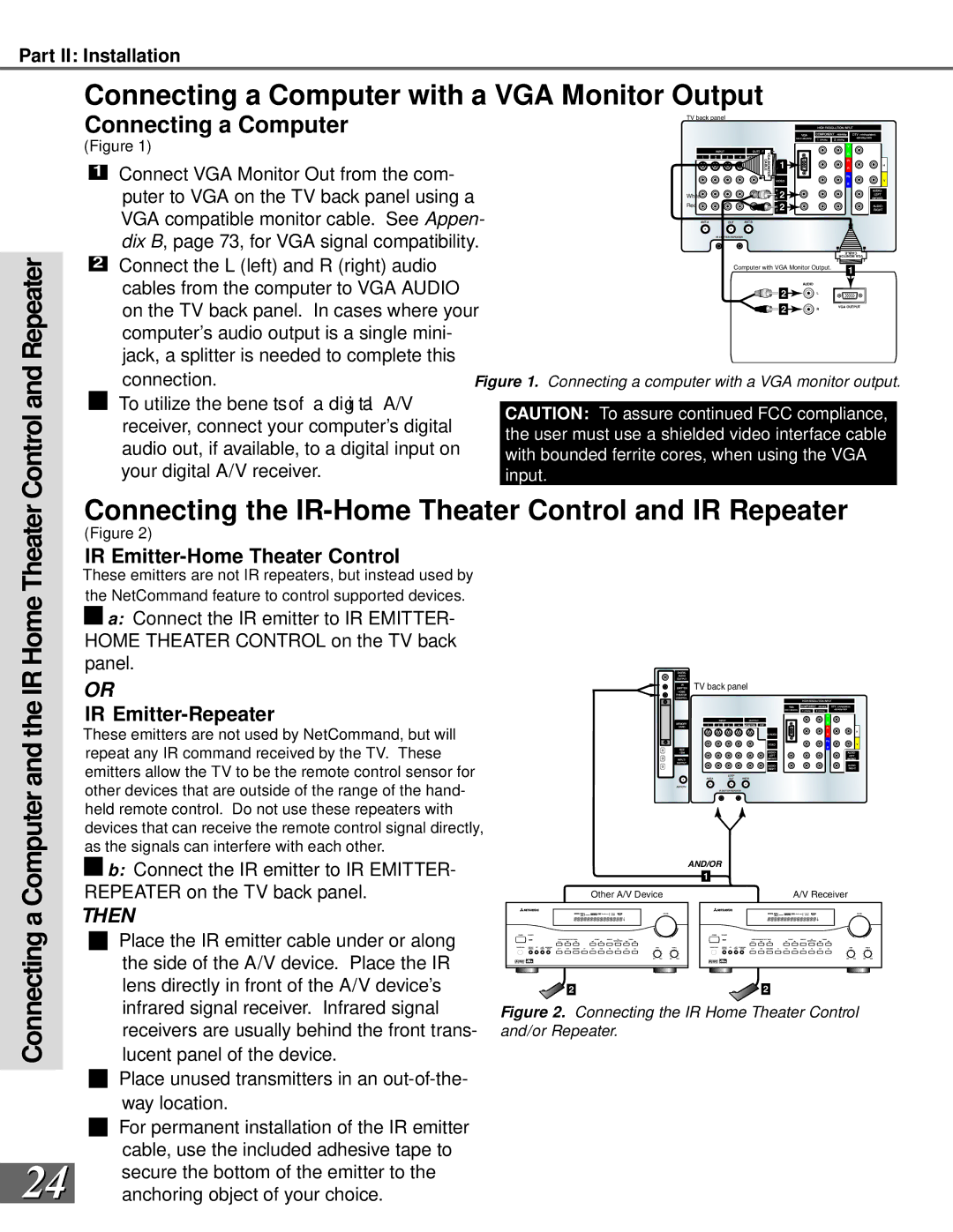
Mitsubishi Electronics WS-65869 Front Control Panel Front Control Panel Functions, System Reset

Page 12

Part II: Installation

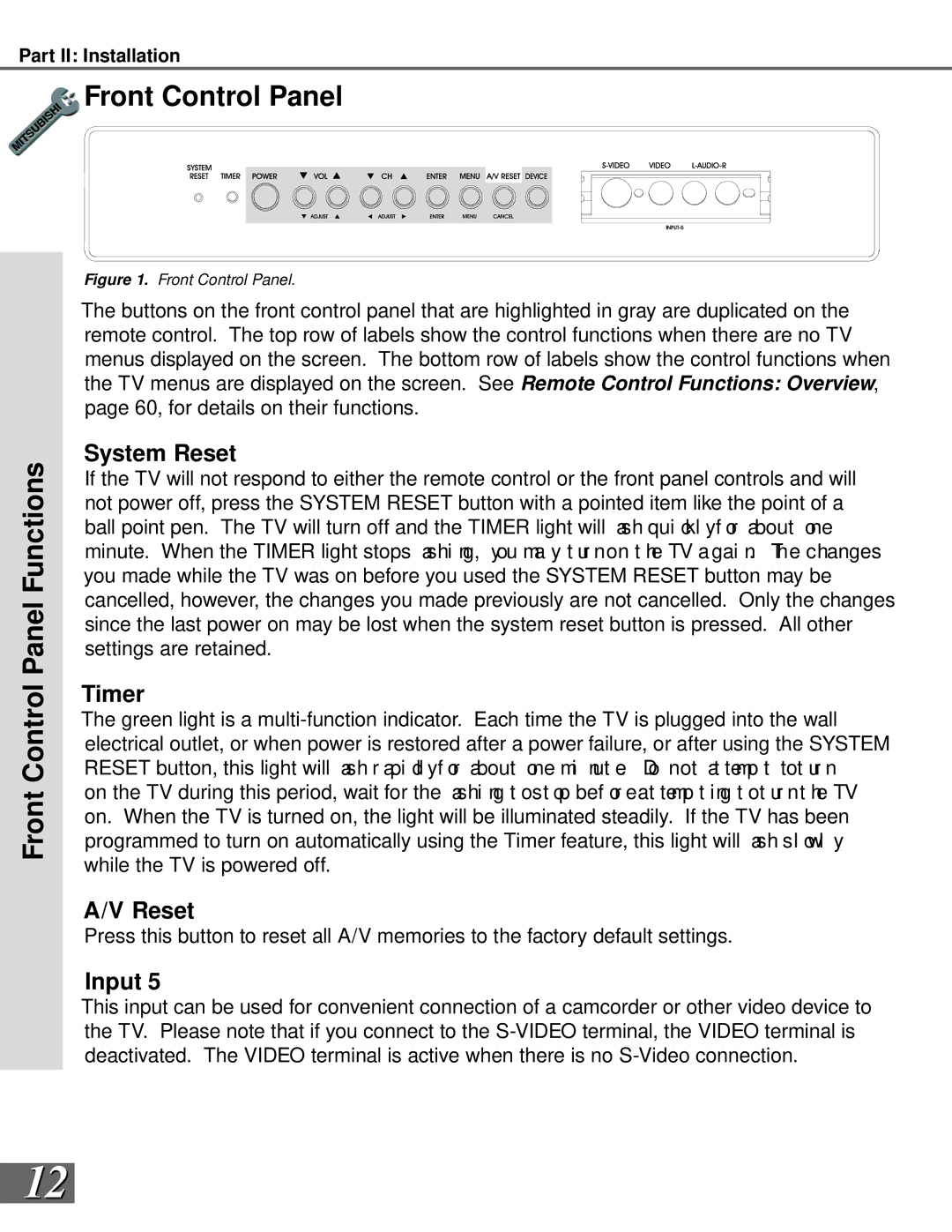
Front Control Panel

Front Control Panel Functions

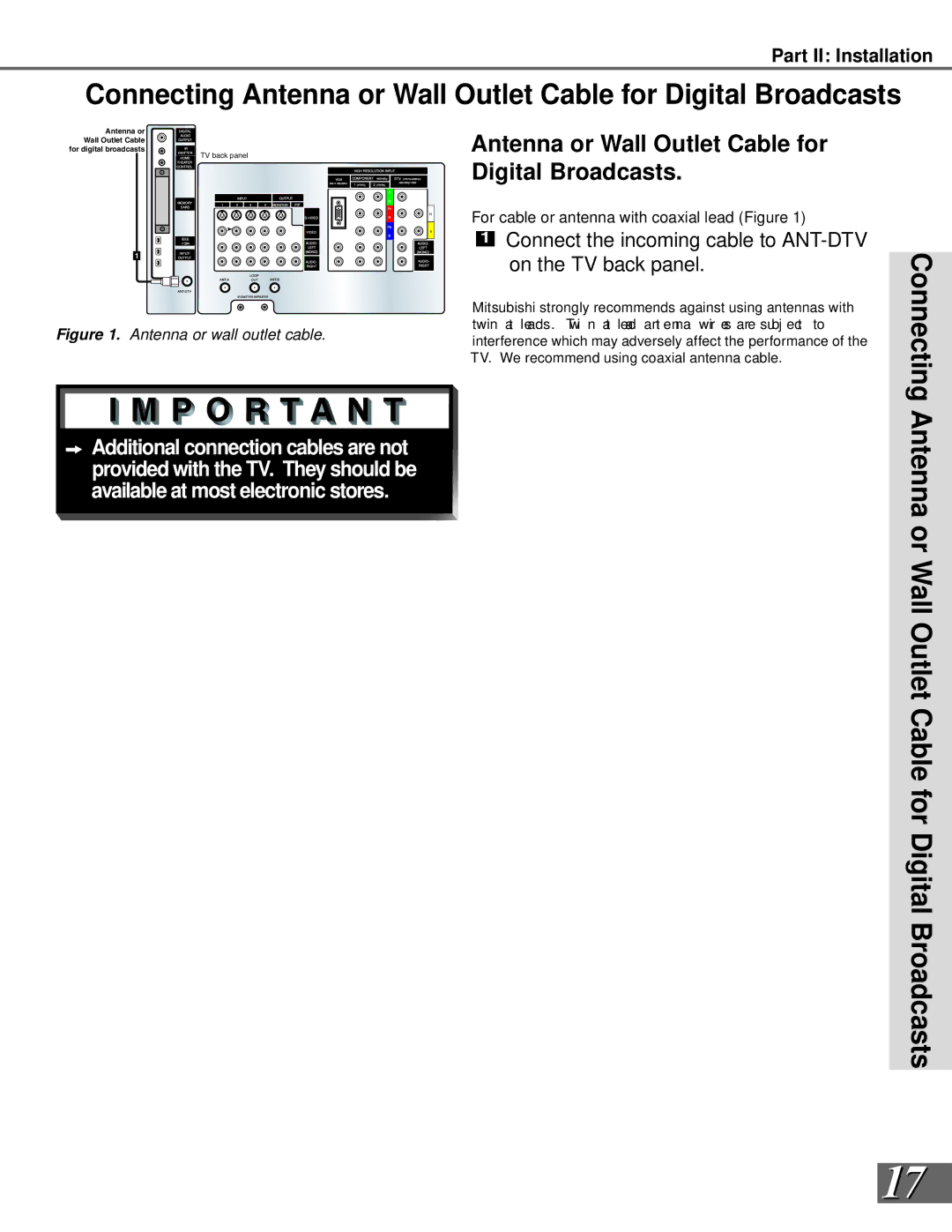
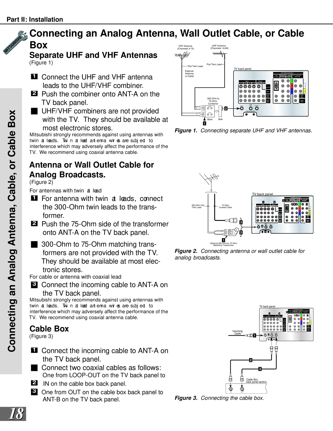
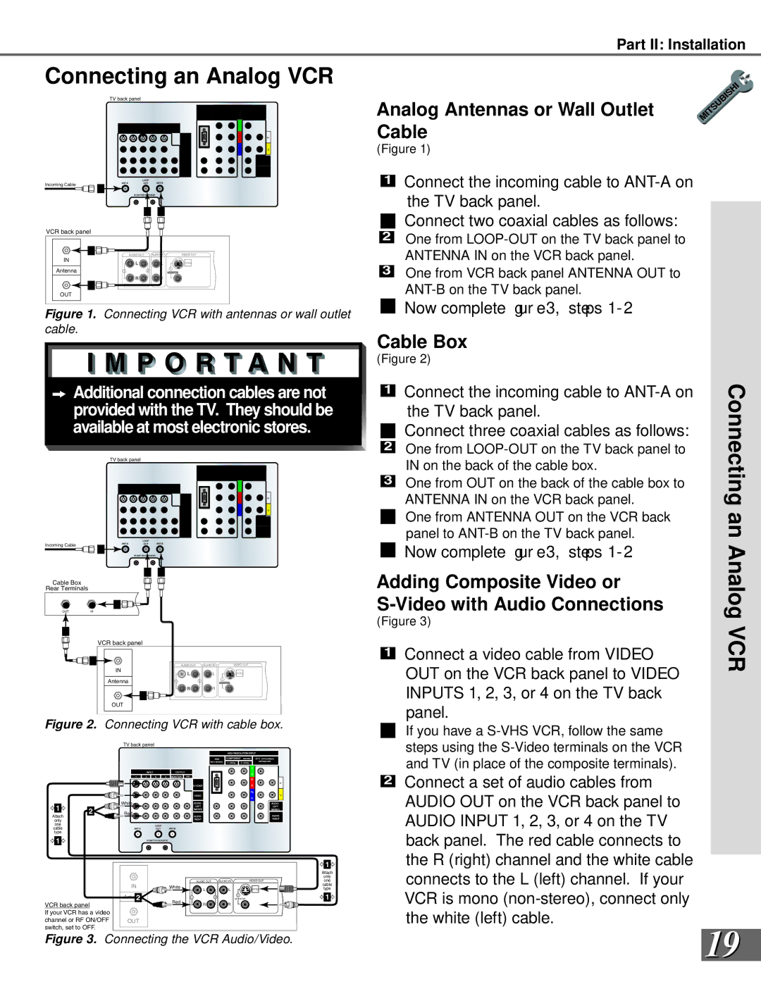
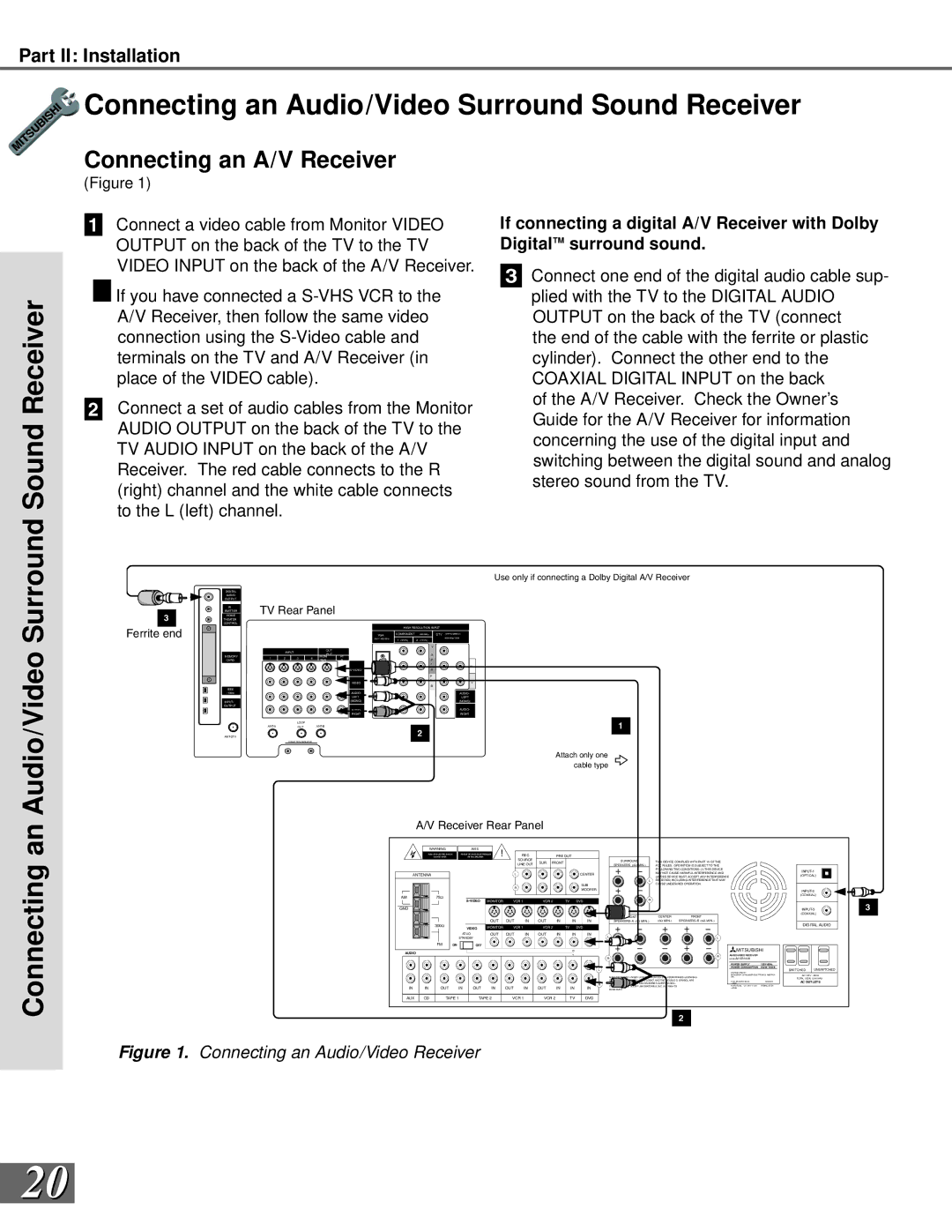
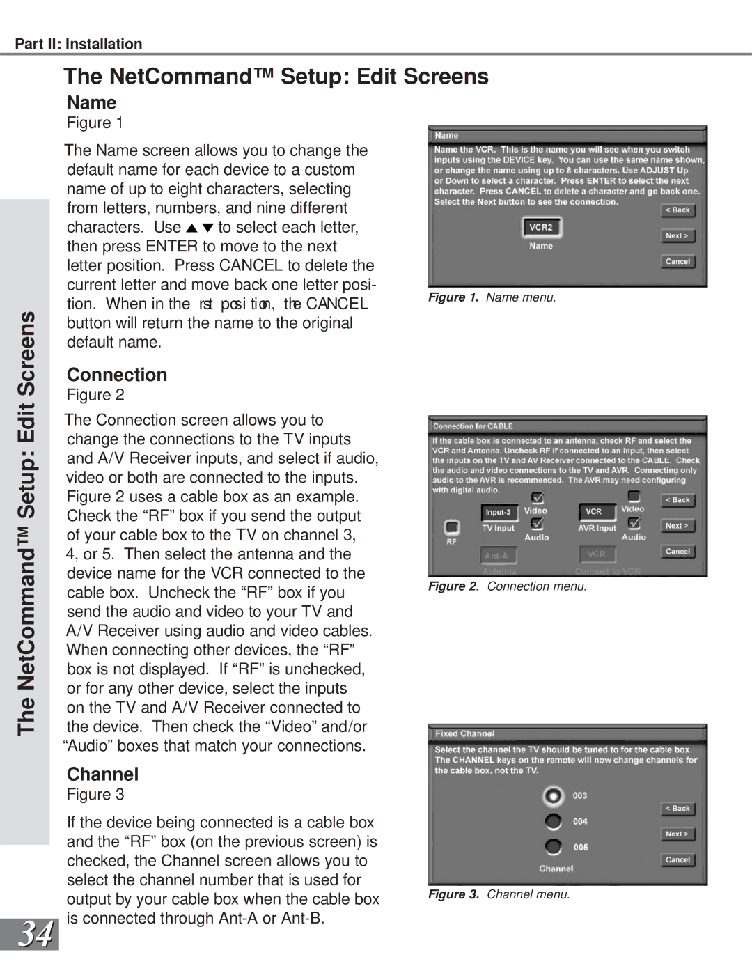
Figure 1. Front Control Panel.

The buttons on the front control panel that are highlighted in gray are duplicated on the remote control. The top row of labels show the control functions when there are no TV menus displayed on the screen. The bottom row of labels show the control functions when the TV menus are displayed on the screen. See Remote Control Functions: Overview, page 60, for details on their functions.

System Reset

If the TV will not respond to either the remote control or the front panel controls and will not power off, press the SYSTEM RESET button with a pointed item like the point of a ball point pen. The TV will turn off and the TIMER light will ash qui ckl yf or about one minute. When the TIMER light stops ashi ng, you ma y t ur n on t he TV agai n. The changes you made while the TV was on before you used the SYSTEM RESET button may be cancelled, however, the changes you made previously are not cancelled. Only the changes since the last power on may be lost when the system reset button is pressed. All other settings are retained.

Timer

The green light is a multi-function indicator. Each time the TV is plugged into the wall electrical outlet, or when power is restored after a power failure, or after using the SYSTEM RESET button, this light will ash r api dl yf or about one mi nut e. Do not at temp t tot ur n

on the TV during this period, wait for the ashi ng t ost op bef or e at temp t ing t ot ur n t he TV on. When the TV is turned on, the light will be illuminated steadily. If the TV has been programmed to turn on automatically using the Timer feature, this light will ash sl owl y while the TV is powered off.

A/V Reset

Press this button to reset all A/V memories to the factory default settings.

Input 5

This input can be used for convenient connection of a camcorder or other video device to the TV. Please note that if you connect to the S-VIDEO terminal, the VIDEO terminal is deactivated. The VIDEO terminal is active when there is no S-Video connection.

12

Image 12
Contents W. m i t s u b i s h i t v. c o m Risk of Electric Shock Do not Open Table of Contents Important Safeguards Important SafeguardsImportant Safeguards SafeguardsMDEAservice@bigscreen . mea . com Thank You We at Mitsubishi Would Like to Thank You Special Features Unpacking Your New TVYour Page Installation System Reset TimerReset Front Control Panel Front Control Panel FunctionsBack Panel Back Panel FunctionsBack Panel Back Panel Functions Installation Con gur at ions & Ne t Co mma ndS e t up NetCommand Supported Devices NetCommand Compatible Legacy DevicesAntenna or Wall Outlet Cable for Digital Broadcasts Connect the incoming cable to ANT-DTV on the TV back panelConnecting an Analog Antenna, Cable, or Cable BoxSeparate UHF and VHF Antennas Antenna or Wall Outlet Cable for Analog BroadcastsConnecting an Analog VCR Analog Antennas or Wall Outlet CableAdding Composite Video or Video with Audio Connections Connecting an Audio/Video Surround Sound Receiver Connecting an A/V ReceiverSurround Sound Receiver Connecting a DVD Player SatelliteDVD Player with Component Video Video VCR or Satellite ReceiverConnecting an External DTV Receiver DTV Connectors and AdaptorsExternal DTV Receiver with Compo- nent Video Connections Connecting an External ReceiverExternal DTV Receiver with RGB Video Connections Connecting a Computer with a VGA Monitor Output Connecting the IR-Home Theater Control and IR RepeaterConnecting a Computer Important Notes Initial Setup Cancel ButtonButtons Back ButtonThis page has been intentionally left blank NetCommand Setup Setup Screens Language ScreenCon gur at ion Sc r een Receiver Screen Cable Box ScreenVCR & VCR2 Screens DBS Screen DVD ScreenCamcorder Screen Review Screen Finish ScreenNetCommand Setup Edit Setup Screens Edit Setup ScreenAdd ChangeNetCommand Setup Edit Screens DeleteReview InitialScreens NetCommand Setup Edit Screens NetCommand Setup EditName ConnectionMonitor Out to AVR or VCR AVR to VCR ConnectionInput-DTV Connection Page Setup 3D Graphical Menu System Menu SystemDevice Selection Menu PIP Selection Menu Selecting Device for PIPSetup Menu Menu Screens OverviewAntenna Menu Clock MenuTimer Menu Captions MenuChip Lock Menu Audio/Video MenuSetup Menu Edit Setup and Icon Position Setup and Icon PositionEdit Setup Button EditConvergence Setup Menu Convergence Reset Factory DefaultsConvergence Convergence ScreenAdvanced Convergence, Transport, and Language Advanced ConvergenceTransport Menu LanguageAntenna Memorize ChannelsMemory Antenna Menu Super Quick View SQV Super Quick View SQVSQV Super Quick View Clock Menu Auto or Manual Clock Setting Manual Clock SettingAuto or Captions Menu Closed Captions Closed CaptionsClosed Captions CC BackgroundChip Lock Menu Passcode LockChip Chip Signal Information Chip Lock Menu V-ChipChip Lock Lock By Time Front Button LockTimer Menu Setting The Timer Setting The TimerTimer On/Off DeviceAudio/Video Settings Menu Settings Menu TV Speakers TV SpeakersTV Speakers Setting Descriptions Audio Audio SettingsSetting Descriptions Video Video SettingsPage Operation Remote Control Functions Overview OverviewRemote Control Functions Care and Operation OperationRemote Control Functions Channel Selection and Sleep Timer Sleep Timer, Operation of PIP and POPRemote Control Functions Operation of PIP and POP Channel Selection Sleep TimerOperation of PIP and POP Display Formats Remote Control Functions Display Formats To Program the Remote to Control NetCommand A/V Products Programming the Remote Control to Control Non-NetCommand To Control Non-NetCommand Programming the Remote ControlRemote Control Functions Special Functions Special FunctionsOther stationary or repetitive computer style images Bypassing the V-Chip Lock Bypassing Front Button LockThis page has been intentionally left blank Input Levels and Timing When Used With RGB Video Signals Component-1 and Component-2 InputsVGA Input Input Connection CompatibilityAppendix C Remote Control Programming Codes ReceiversDVD Players Satellite ReceiversCleaning Appendix D Cleaning and ServiceService Diamond Shield Installation Appendix E Diamond Shield Installation WS-55909, and, WS-73909Appendix F Cabinet Separation for Model WS-65869 For Problem Possible Solution Appendix G TroubleshootingAppendix G Troubleshooting Problem Possible Solution TV will not turn on after being pluggedIndex Index S-W Stationary PictureMitsubishi Projection TV Limited Warranty Mitsubishi Projection TV Limited WarrantyPage Page Mitsubishi Digital Electronics America, Inc 871D330B10