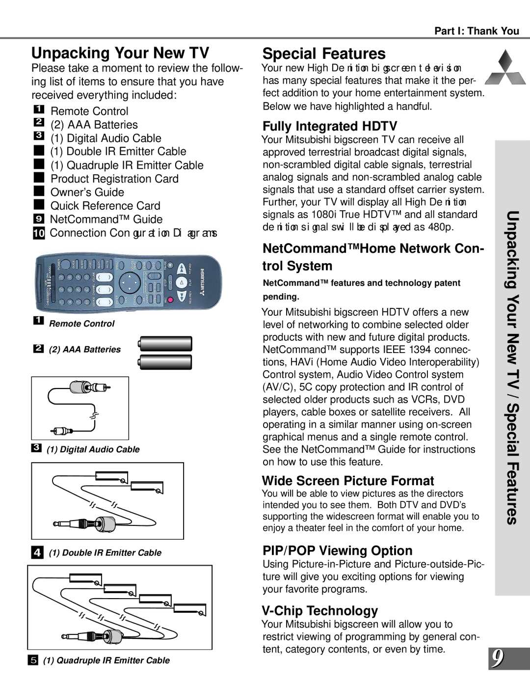
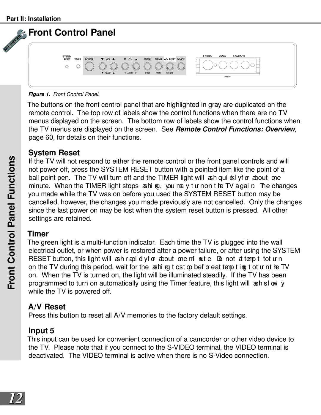
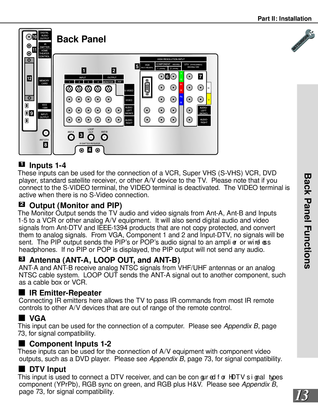
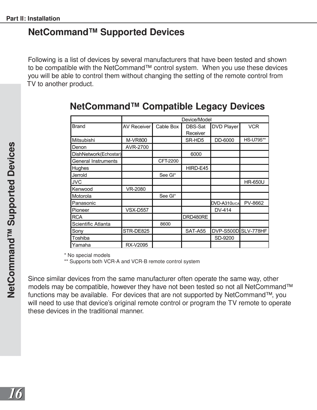
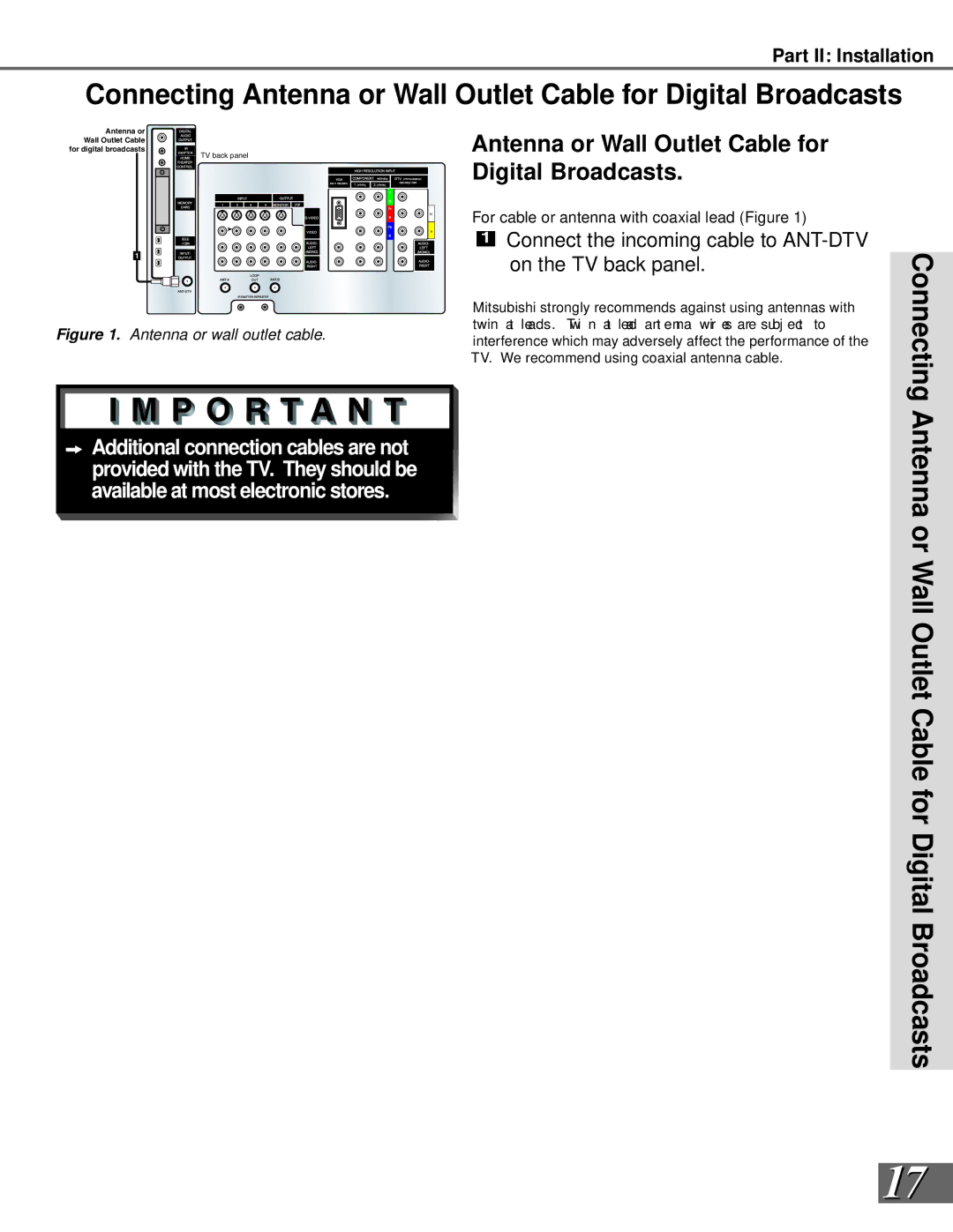
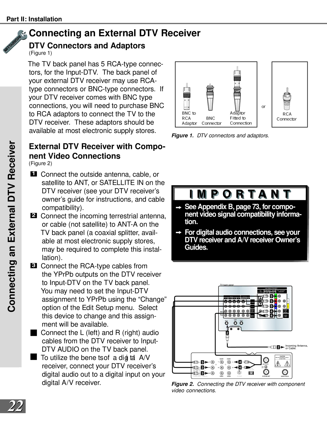
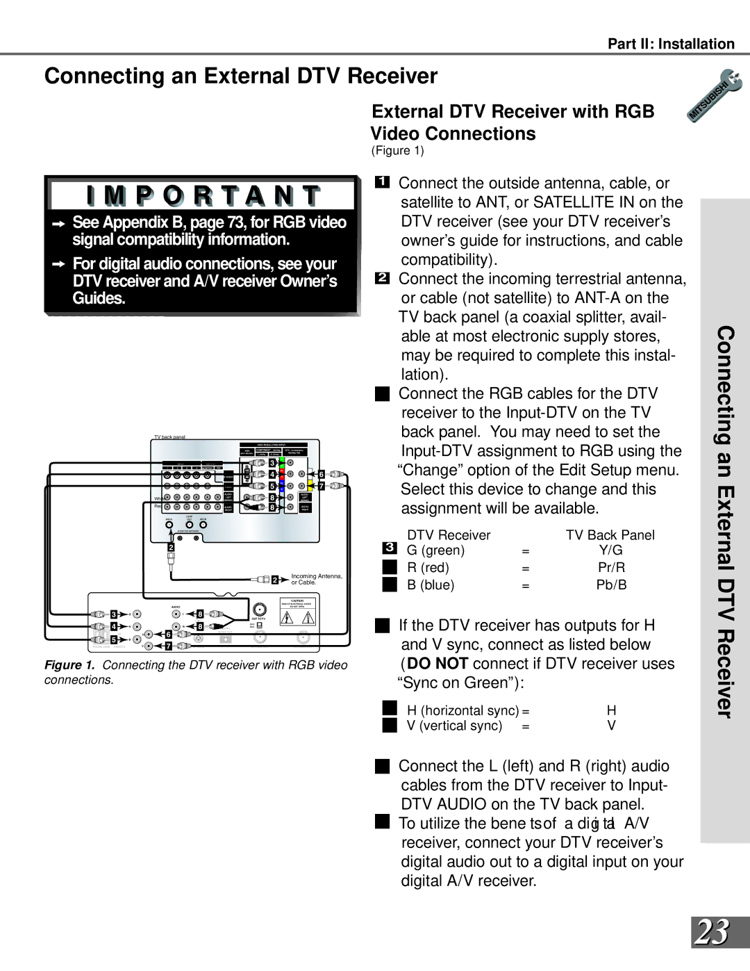
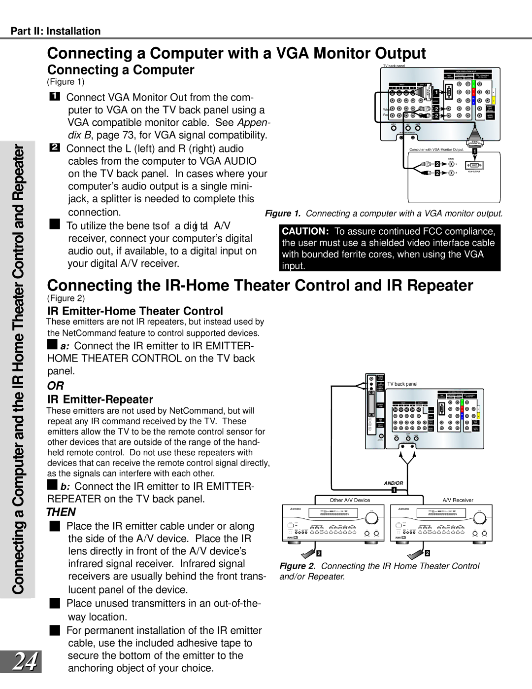
Mitsubishi Electronics WS-65909, WS-73909, WS-65869, WS-55859 Connecting a DVD Player, Satellite

Page 21

Part II: Installation

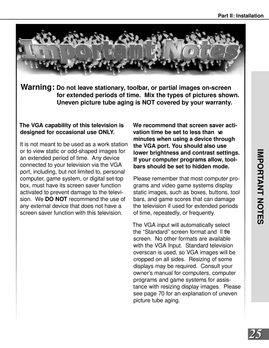
WARNING: Do not display the same stationary images on the screen for more that 15% of your total TV viewing in one week. Examples of stationary images are

letterbox top/bottom bars from DVD or other video sources, side bars when showing standard TV pictures on widescreen TV’s, stock market reports, video game patterns, station logos, web sites, or stationary computer images. Such patterns can unevenly age the picture tubes causing permanent damage to the TV. Please see page 70 for a detailed explanation.

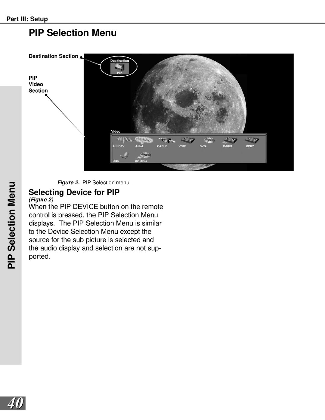
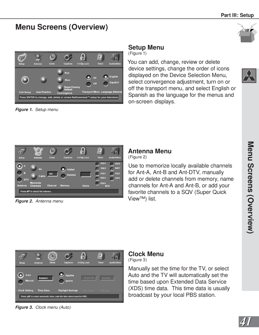
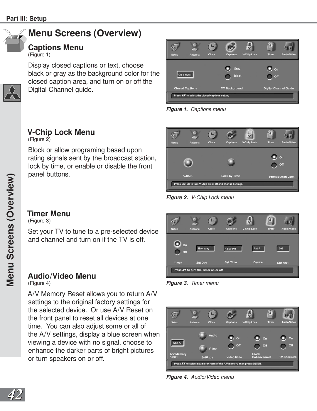
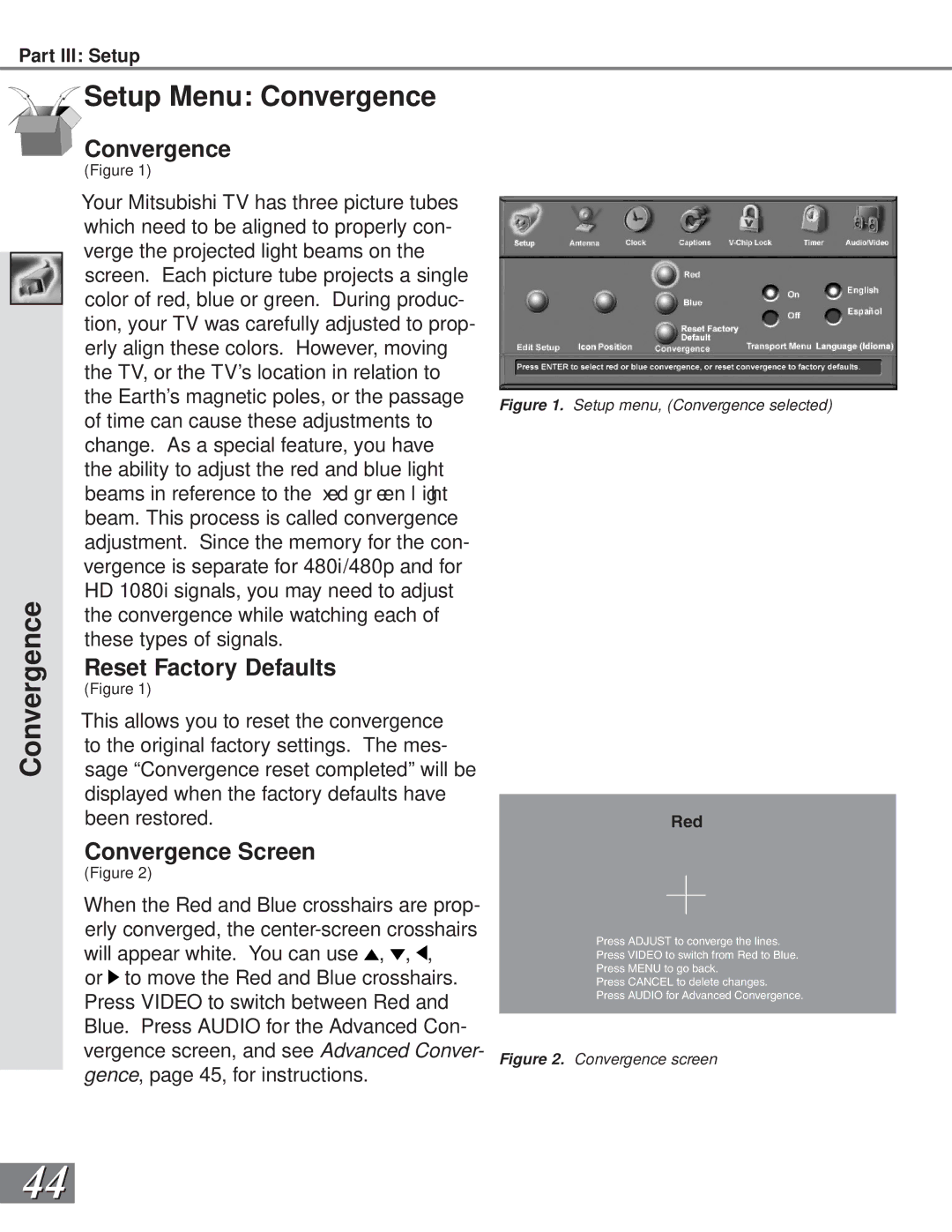
Connecting a DVD Player

TV back panel


1


2


3

White

5

Red

4


DVD back panel

1


AUDIO OUT


AC IN

Y

VIDEO


5.1 CH SURROUND

2CH

BITSTREAM/PCM

MITSUBISHI


DVD PLAYER


2


White

CENTER


MODEL DD-5000


CB


5


L

POWER SUPPLY

120V~ 60Hz


S


POWER CONSUMPTION

20W

3


4


CR


Red


R

DISTRIBUTED BY


MITSUBISHI DIGITAL ELECTRONICS


AMERICA, INC.


VIDEO OUT

SUBWOOFER SURROUND FRONT


COAXIAL OPTICAL

9351 JERONIMO ROAD


IRVINE, CA 92618


MADE IN JAPAN

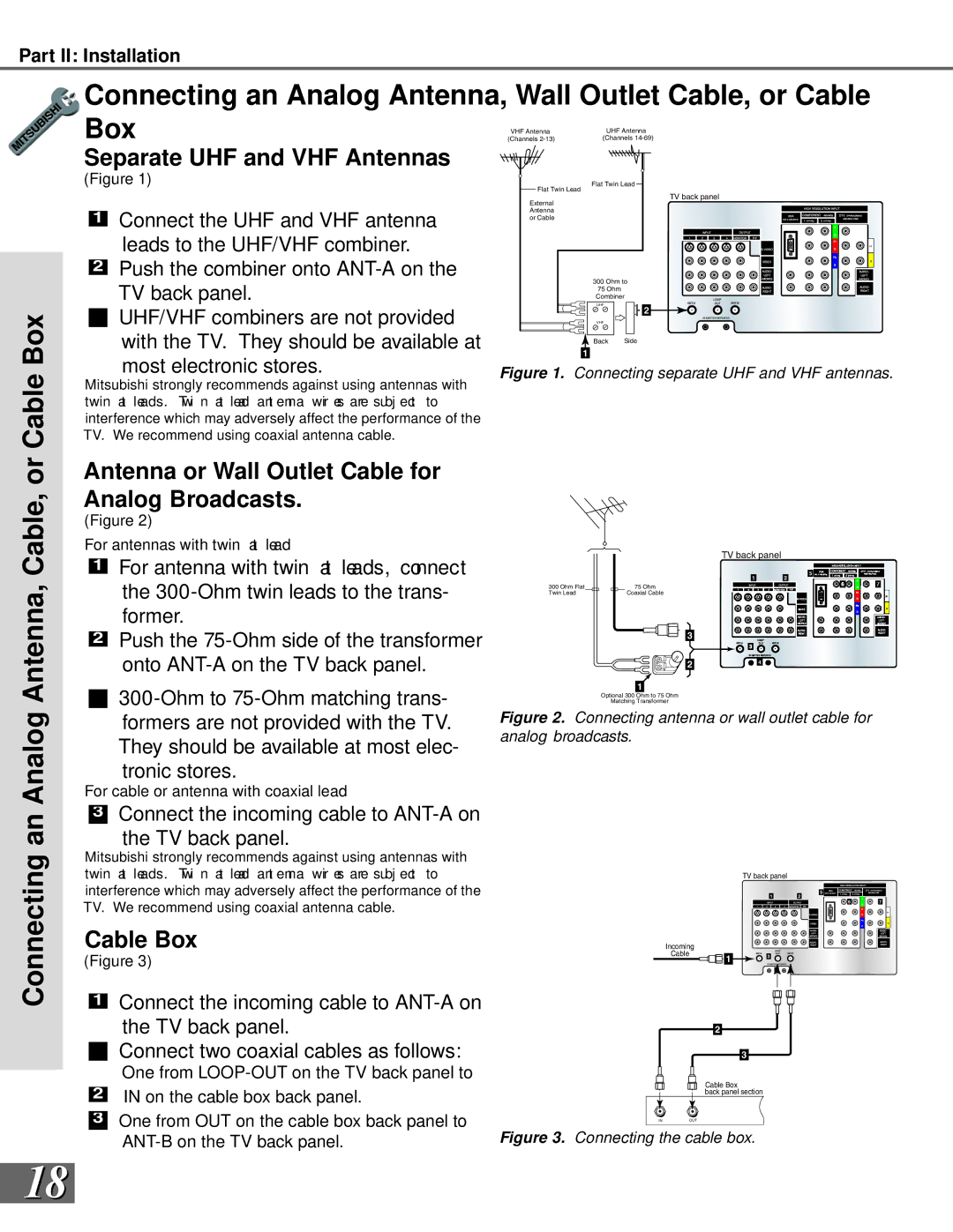
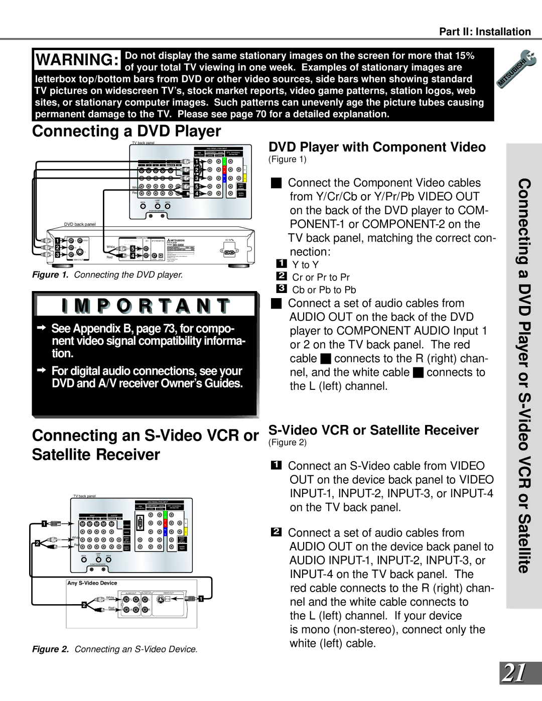
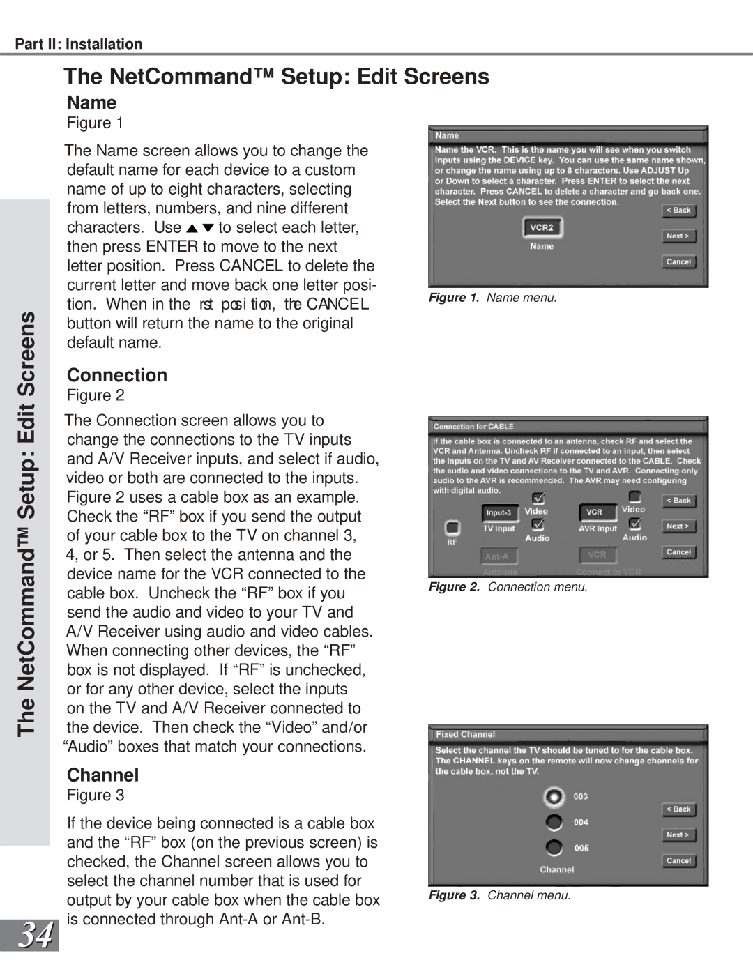
Figure 1. Connecting the DVD player.

See Appendix B, page 73, for compo- nent video signal compatibility informa- tion.

For digital audio connections, see your DVD and A/V receiver Owner’s Guides.

DVD Player with Component Video

(Figure 1)

Connect the Component Video cables from Y/Cr/Cb or Y/Pr/Pb VIDEO OUT on the back of the DVD player to COM- PONENT-1 or COMPONENT-2 on the TV back panel, matching the correct con- nection:

1Y to Y

2Cr or Pr to Pr

3Cb or Pb to Pb

Connect a set of audio cables from AUDIO OUT on the back of the DVD player to COMPONENT AUDIO Input 1 or 2 on the TV back panel. The red cable 4 connects to the R (right) chan- nel, and the white cable 5 connects to the L (left) channel.

Connecting a DVD Player or S-

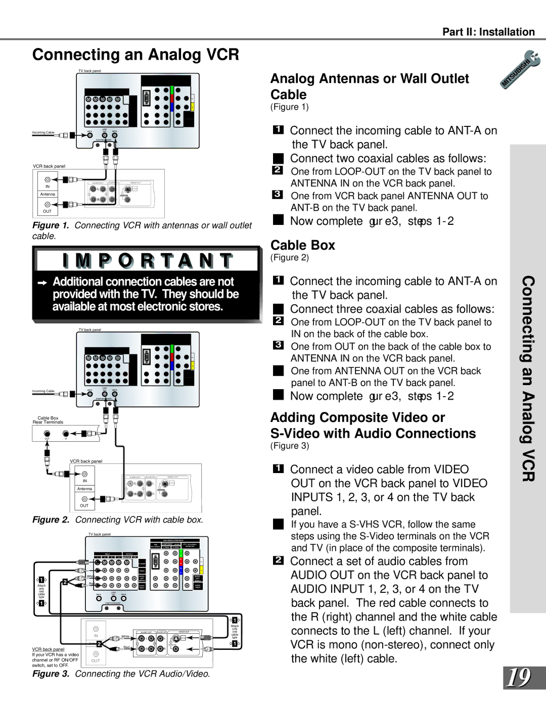
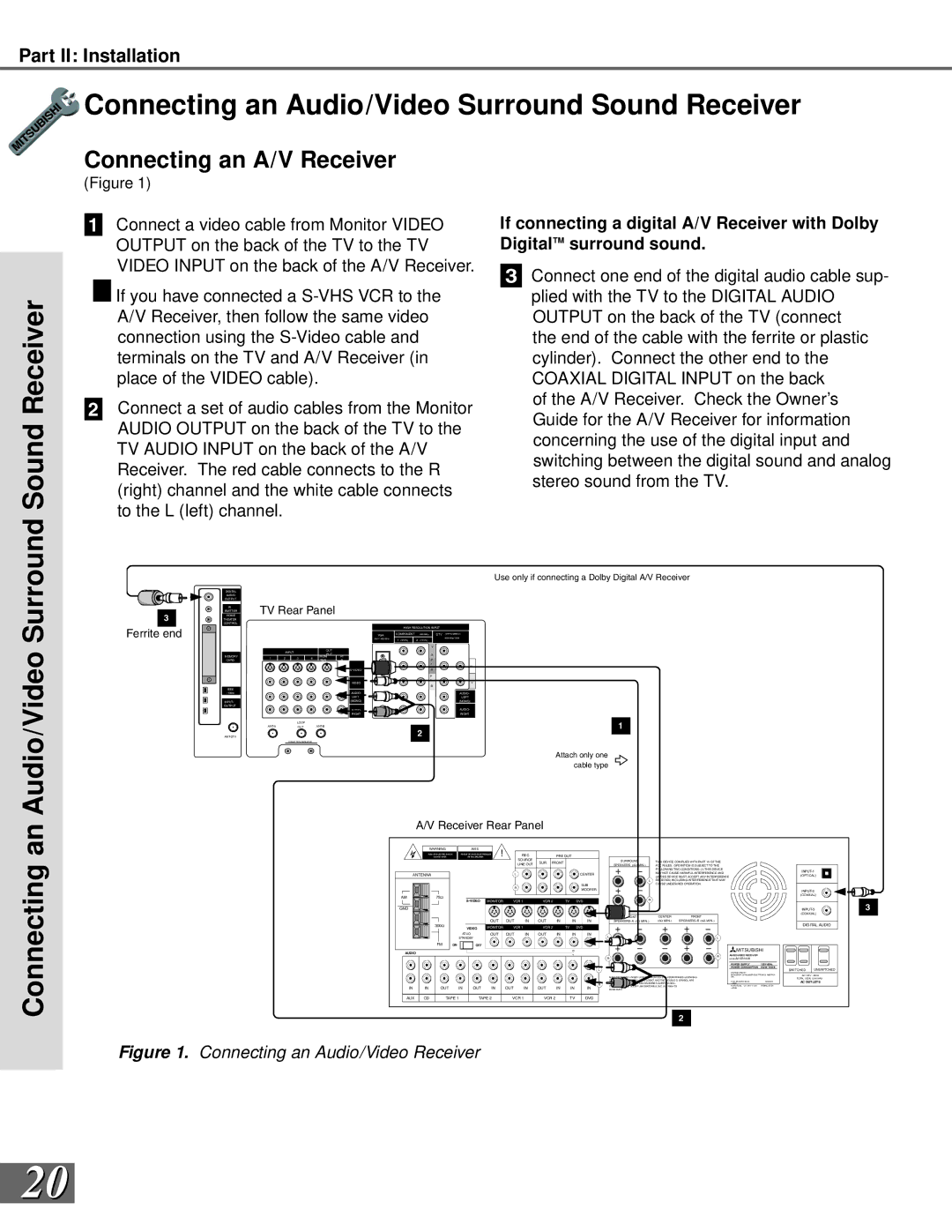
Connecting an S-Video VCR or Satellite Receiver

TV back panel

S-Video VCR or Satellite Receiver

(Figure 2)

1Connect an S-Video cable from VIDEO OUT on the device back panel to VIDEO INPUT-1, INPUT-2, INPUT-3, or INPUT-4 on the TV back panel.

Video VCR or


1


White

2

Red

Any S-Video Device


AUDIO OUT

AUDIO IN

VIDEO OUT


White

L

L

(Y/C)

1

2

1

2


Red

R

R


Figure 2. Connecting an S-Video Device.

2

Connect a set of audio cables from AUDIO OUT on the device back panel to AUDIO INPUT-1, INPUT-2, INPUT-3, or INPUT-4 on the TV back panel. The red cable connects to the R (right) chan- nel and the white cable connects to the L (left) channel. If your device

is mono (non-stereo), connect only the white (left) cable.

Satellite

21
Image 21
Contents W. m i t s u b i s h i t v. c o m Risk of Electric Shock Do not Open Table of Contents Important Safeguards Important SafeguardsSafeguards Important SafeguardsMDEAservice@bigscreen . mea . com Thank You We at Mitsubishi Would Like to Thank You Special Features Unpacking Your New TVYour Page Installation Timer System ResetReset Front Control Panel Front Control Panel FunctionsBack Panel Functions Back PanelBack Panel Back Panel Functions Installation Con gur at ions & Ne t Co mma ndS e t up NetCommand Compatible Legacy Devices NetCommand Supported DevicesConnect the incoming cable to ANT-DTV on the TV back panel Antenna or Wall Outlet Cable for Digital BroadcastsCable Box Connecting an Analog Antenna, Cable, orSeparate UHF and VHF Antennas Antenna or Wall Outlet Cable for Analog BroadcastsConnecting an Analog VCR Analog Antennas or Wall Outlet CableAdding Composite Video or Video with Audio Connections Connecting an Audio/Video Surround Sound Receiver Connecting an A/V ReceiverSurround Sound Receiver Satellite Connecting a DVD PlayerDVD Player with Component Video Video VCR or Satellite ReceiverConnecting an External DTV Receiver DTV Connectors and AdaptorsExternal DTV Receiver with Compo- nent Video Connections Connecting an External ReceiverExternal DTV Receiver with RGB Video Connections Connecting a Computer with a VGA Monitor Output Connecting the IR-Home Theater Control and IR RepeaterConnecting a Computer Important Notes Cancel Button Initial SetupButtons Back ButtonThis page has been intentionally left blank NetCommand Setup Setup Screens Language ScreenCon gur at ion Sc r een Receiver Screen Cable Box ScreenVCR & VCR2 Screens DBS Screen DVD ScreenCamcorder Screen Finish Screen Review ScreenEdit Setup Screen NetCommand Setup Edit Setup ScreensAdd ChangeDelete NetCommand Setup Edit ScreensReview InitialNetCommand Setup Edit Screens NetCommand Setup Edit ScreensName ConnectionMonitor Out to AVR or VCR AVR to VCR ConnectionInput-DTV Connection Page Setup Menu System 3D Graphical Menu SystemDevice Selection Menu Selecting Device for PIP PIP Selection MenuMenu Screens Overview Setup MenuAntenna Menu Clock MenuCaptions Menu Timer MenuChip Lock Menu Audio/Video MenuSetup and Icon Position Setup Menu Edit Setup and Icon PositionEdit Setup Button EditReset Factory Defaults Convergence Setup Menu ConvergenceConvergence Convergence ScreenAdvanced Convergence Advanced Convergence, Transport, and LanguageTransport Menu LanguageAntenna Memorize ChannelsMemory Antenna Menu Super Quick View SQV Super Quick View SQVSQV Super Quick View Clock Menu Auto or Manual Clock Setting Manual Clock SettingAuto or Closed Captions Captions Menu Closed CaptionsClosed Captions CC BackgroundChip Lock Menu Passcode LockChip Chip Signal Information Chip Lock Menu V-ChipChip Lock Front Button Lock Lock By TimeSetting The Timer Timer Menu Setting The TimerTimer On/Off DeviceAudio/Video Settings Menu Settings Menu TV Speakers TV SpeakersTV Speakers Audio Settings Setting Descriptions AudioVideo Settings Setting Descriptions VideoPage Operation Overview Remote Control Functions OverviewOperation Remote Control Functions Care and OperationSleep Timer, Operation of PIP and POP Remote Control Functions Channel Selection and Sleep TimerRemote Control Functions Operation of PIP and POP Channel Selection Sleep TimerOperation of PIP and POP Display Formats Remote Control Functions Display Formats To Program the Remote to Control NetCommand A/V Products Programming the Remote Control to Control Non-NetCommand Programming the Remote Control To Control Non-NetCommandSpecial Functions Remote Control Functions Special FunctionsOther stationary or repetitive computer style images Bypassing Front Button Lock Bypassing the V-Chip LockThis page has been intentionally left blank Component-1 and Component-2 Inputs Input Levels and Timing When Used With RGB Video SignalsVGA Input Input Connection CompatibilityReceivers Appendix C Remote Control Programming CodesDVD Players Satellite ReceiversAppendix D Cleaning and Service CleaningService Diamond Shield Installation WS-55909, and, WS-73909 Appendix E Diamond Shield InstallationAppendix F Cabinet Separation for Model WS-65869 For Appendix G Troubleshooting Problem Possible SolutionTV will not turn on after being plugged Appendix G Troubleshooting Problem Possible SolutionIndex Stationary Picture Index S-WMitsubishi Projection TV Limited Warranty Mitsubishi Projection TV Limited WarrantyPage Page Mitsubishi Digital Electronics America, Inc 871D330B10