Sierra SL-800 instruction manual Calibration of Mass Flow Meters MFMs

Page 16

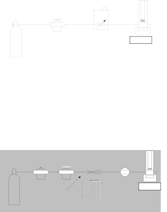
GasAdjustable

SupplyRegulator

MFC

DryCal

Cal=Trak

Figure 11 Setup for Calibrating MFCs

7.7Calibration of Mass Flow Meters (MFMs)

Mass flow meters can be calibrated with the setup of Figure 12, which is similar to that shown for LFE transfer standards. Again, the flow must not be affected significantly by the Cal=Trak’s cyclic pressure increase. This can be achieved by use of a sonic nozzle as the stable flow source, or by feeding a fixed restrictor with a precisely regulated pressure of more than 200 kPa. (At 200 kPa [30 PSI], the dynamic flow decrease caused by the piston’s weight will be about 0.05%.) Alternately, a stable mass flow controller may be used to maintain specific flows into the MFM under test. In this scenario, the MFC will function as a pressure stabilizer and precision flow regulator with the Cal=Trak defining the accuracy of the device under test. Contact Sierra Instruments for special Smart-Trak flow controllers designed for this application.

If the MFM under test must be calibrated at pressure (i.e. because it is always used under pressure) then a fine resolution valve (needle valve) and a gauge should be installed between the MFM and the Cal=Trak. Adjust the valve until the pressure gauge reads the correct pressure for the MFM under test.

GasFixed Adjustable Sonic

Supply Regulator Regulator Nozzle

Flow Meter

Stable Pressure

OR Porous Plug


> 200 kPa


OR MFC


Figure 12 Setup for Calibrating Mass Flow Meters

Cal=TraDryCalk

7.8Calibration of Rotameters (Variable Area Flow Meters)

Variable-area meters can become unstable when connected in series with a volume. Cavity resonance may even occur. They are best calibrated using the setup of Figure 13. The flow stream is alternately applied to the Cal=Trak and to the device under test. A sonic nozzle or a large “swamping” pressure restriction is used to render the differences in the two devices’ insertion pressures insignificant with respect to the required accuracy.

16

Image 16
Contents Cal=Trak SL-800 Primary Gas Flow Calibrator Worldwide Locations to Serve You Table of Contents Page General Description Theory of OperationIdealized Automatic Piston Prover Cal=Trak Layout Unpacking Checklist Your Cal=Trak SL-800 Base IncludesEach of Your Cal=Trak SL-800 Flow Cells Includes Cal=Trak Installation Attaching & Removing Flow Cells Connecting the Cal=Trak to a Flow SourceCal=Trak Measurement Cycle Attaching Flow CellsInitial Pressure Pulse Timing KPa Begins Ends Application Precautions Inventory Dead VolumeComparison vs. Calibration Initial Pressure PulseSetup for Piston or Bell Provers Alternative Setup for Piston Provers Vacuum Comparison of Cal=Trak with Piston or Bell ProversSetup for LFEs Comparison of Cal=Trak with Sonic Nozzle Transfer StandardsVacuum Setup for Sonic Nozzle Transfer Standard Calibration of Mass Flow Controllers MFCsCalibration of Mass Flow Meters MFMs Calibration of Rotameters Variable Area Flow MetersCharging the Cal=Trak Battery Operating InstructionsTurning the Cal=Trak On Turning the Cal=Trak OffLow Battery Indicator Cal=Trak Keypad How To Use the Cal=Trak KeypadGeneral Menu Navigation Parameters Factory Settings Optional Settings Factory Default SettingsTaking Readings Setting User Preferences Option 1, Sensor FactorSetup Menu 2, Reading Type, # in Average & Minutes/Reading Setup Menu 4, Date, Time & Battery VoltageSetup Menu 5, Date & Time Formats Option 1, DateOption 2, Time Option 3, Auto OffBattery Maintenance & Storage Battery SystemMaintenance Quality Assurance Leak Test Procedure To Initiate the Leak TestCalibration Leak Test Illustration Leak Test in ProgressReturning Your Unit for Calibration or Service Shipment Replacement Parts & AccessoriesCalibration Includes Part DescriptionAdditional Information Limited Warranty Charge LED does not light when charger plugged Settings have been lost or seem to have changedPiston Error appears on display Unit suddenly turns offWhen taking readings, the flow seems off Piston does not move when the Read or Auto is pushedDuring Leak Test, Leakage 9.999 ccm appears on display Resetting the Cal=Trak Contact Sierra for AssistanceModel Optimum Flow Range Flow Cell Standardized 15-30CInstallation Operating Instructions for Cal=Soft Software IntroductionRequirements Worksheet descriptionsSetup Cal=Trak IntroductionSetup DUT Setup Cal=SoftPage Page Automatic Flow Calibration Using Sierra 100 Series MFC Serial Port Selection Issue Software TroubleshootingSerial Port Configuration Issue