Teledyne 3300PA operating instructions Cell Warranty Conditions

Page 32

5 Maintenance

Model 3300PA


CAUTION: Do not scratch, puncture, or damage the sensing membrane of the Micro-Fuel Cell sensor. Damage to the membrane will require replacement of the sensor.

1.Disconnect the Power Source from the Unit.

2.Remove the new Micro-Fuel Cell from its protective bag, being careful not to lose the O-ring at the base of the threaded portion of the cell.

3.Open Sensor Housing door on the front panel.

4.Replace the cell on the cell holder by screwing it clockwise into the cell block until it is held firmly in the socket.

5.Insert the cell block electrical connector plug into the socket in the sensor.

5.2.5 Cell Warranty Conditions

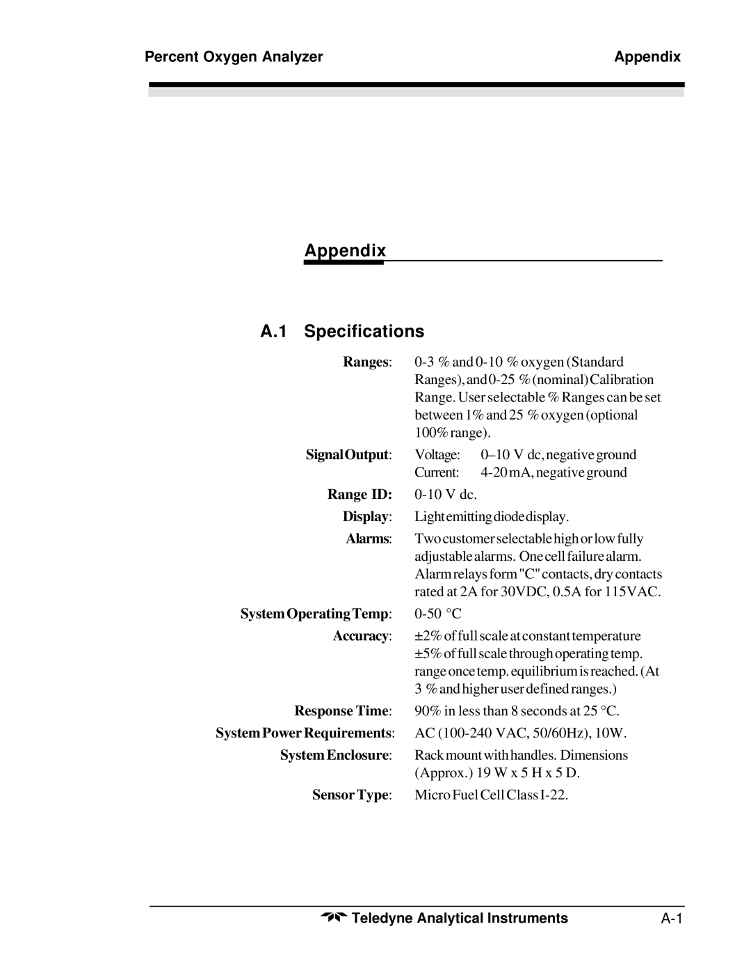
The Class I-22 Micro-Fuel cell is used in the Model 3300PA. This cell is a long life cell and is warranted for 2 years (under specified operating condi- tions—see Appendix) from the date of shipment. Note any Addenda attached to the front of this manual for special information applying to your instrument.

With regard to spare cells, warranty period begins on the date of shipment. The customer should stock only one spare cell per instrument at a time. Do not attempt to stockpile spare cells.

If a cell was working satisfactorily, but ceases to function before the warranty period expires, the customer will receive credit toward the purchase of a new cell.

If you have a warranty claim, you must return the cell in question to the factory for evaluation. If it is determined that failure is due to faulty workmanship or material, the cell will be replaced at no cost to the customer.

NOTE: Evidence of damage due to tampering or mishandling will render the cell warranty null and void.

5-4

Teledyne Analytical Instruments

Image 32
Contents Model 3300PA Copyright 1999 Teledyne Analytical Instruments Contents Maintenance AppendixCombustible GAS Usage Warning This page left intentionally blank Percent Oxygen Analyzer Introduction Main Features of the AnalyzerIntroduction Overview Front Panel Description Introduction Model 3300PARear Panel Description Rear PanelAnalog Outputs Operational Theory Introduction Micro-Fuel Cell SensorPercent Oxygen Analyzer Operational Theory Principles of OperationOperational Theory Model 3300PA Anatomy of a Micro-Fuel CellElectrochemical Reactions Effect of PressureCalibration Characteristics Characteristic Input/Output Curve for a Micro-Fuel CellGeneral Signal ProcessingElectronics Operational Theory Model 3300PA Unpacking the Analyzer InstallationPercent Oxygen Analyzer Installation Installation Model 3300PA Control Unit InstallationInstalling the Micro-Fuel Cell Location and MountingPercent Oxygen Analyzer Installation Gas Connections Sensor FailVacuum Service Option Installation Checklist Installation Model 3300 PAOperation Introduction Percent Oxygen Analyzer OperationOperation Model 3300PA Using the Function and Data Entry ButtonsSetting the Analysis Ranges Setting the Alarm Setpoints Set AlarmPercent Oxygen Analyzer Operation HI Range LO RangeSensor Fail Alarm Selecting a Fixed Range or Autoranging CalibrationSupplementary Information Maintenance Percent Oxygen Analyzer MaintenanceRemove Power to Unit before replacing the fuse Replacing the FuseSensor Installation or Replacement Maintenance Model 3300PAWhen to Replace a Sensor Ordering and Handling of Spare SensorsInstalling a Micro-Fuel Cell Removing the Micro-Fuel CellCell Warranty Conditions Appendix Specifications Percent Oxygen Analyzer AppendixSpare Parts List Appendix Model 3300PAReference Drawing MiscellaneousAppendix Model 3300PA