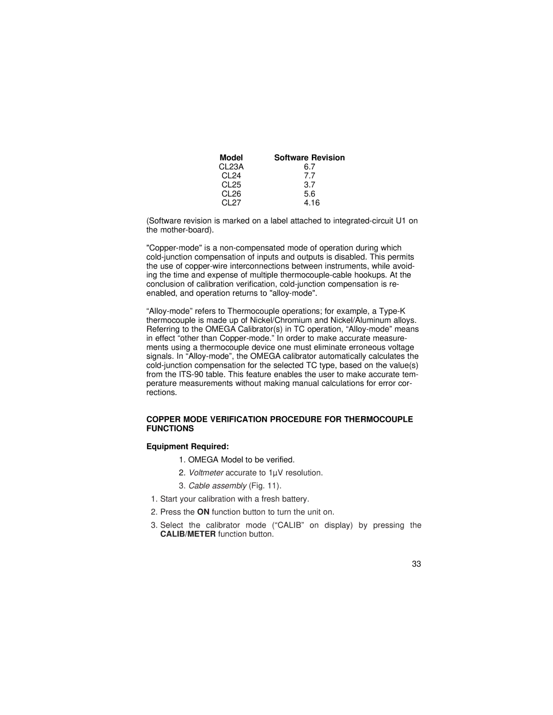
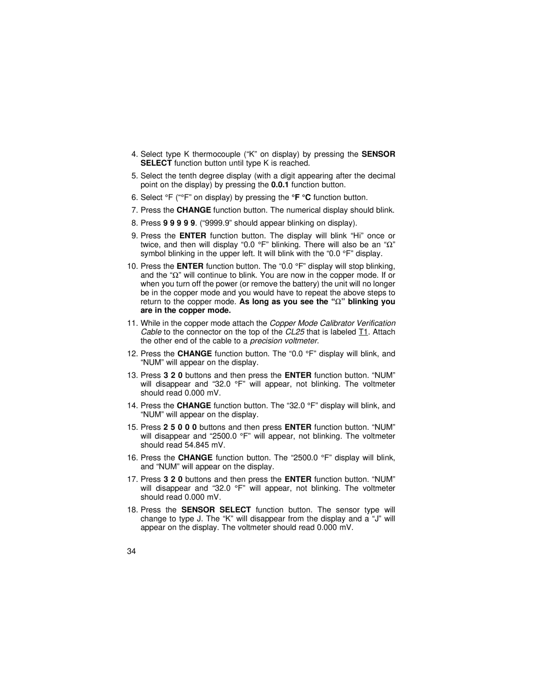
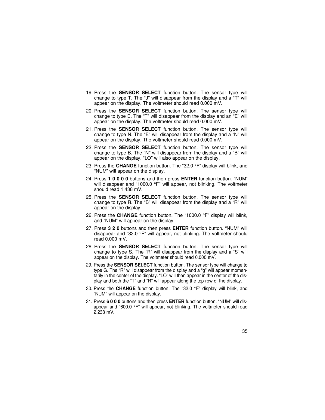
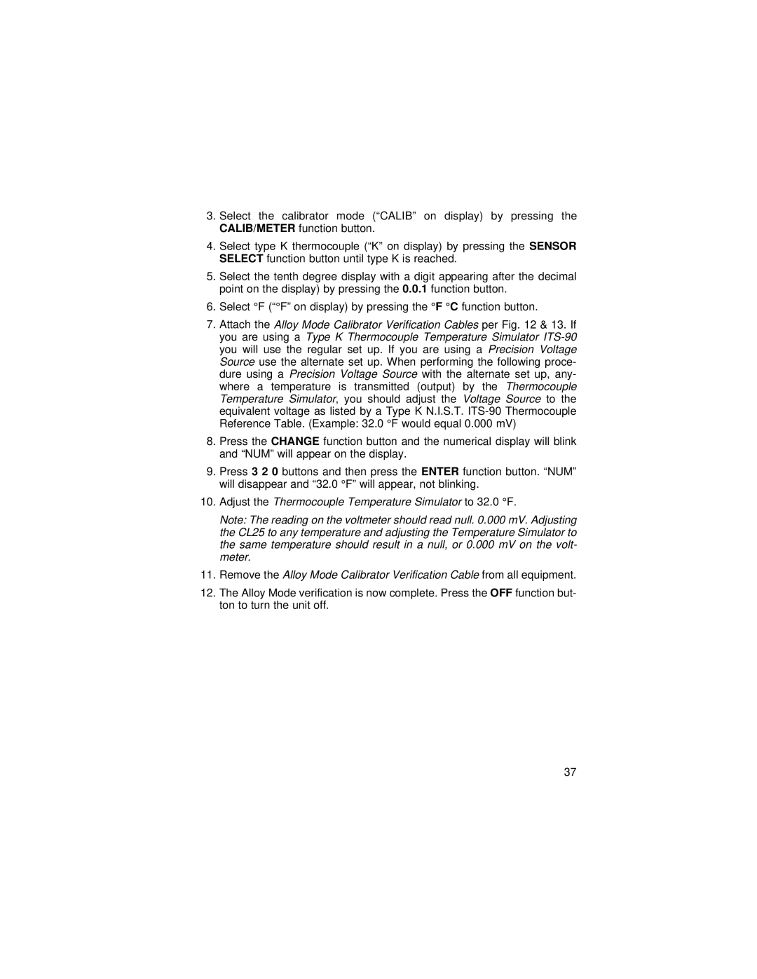
Omega 26, 24 manual Step Function, Ramp Function CL25 and CL27

Page 24

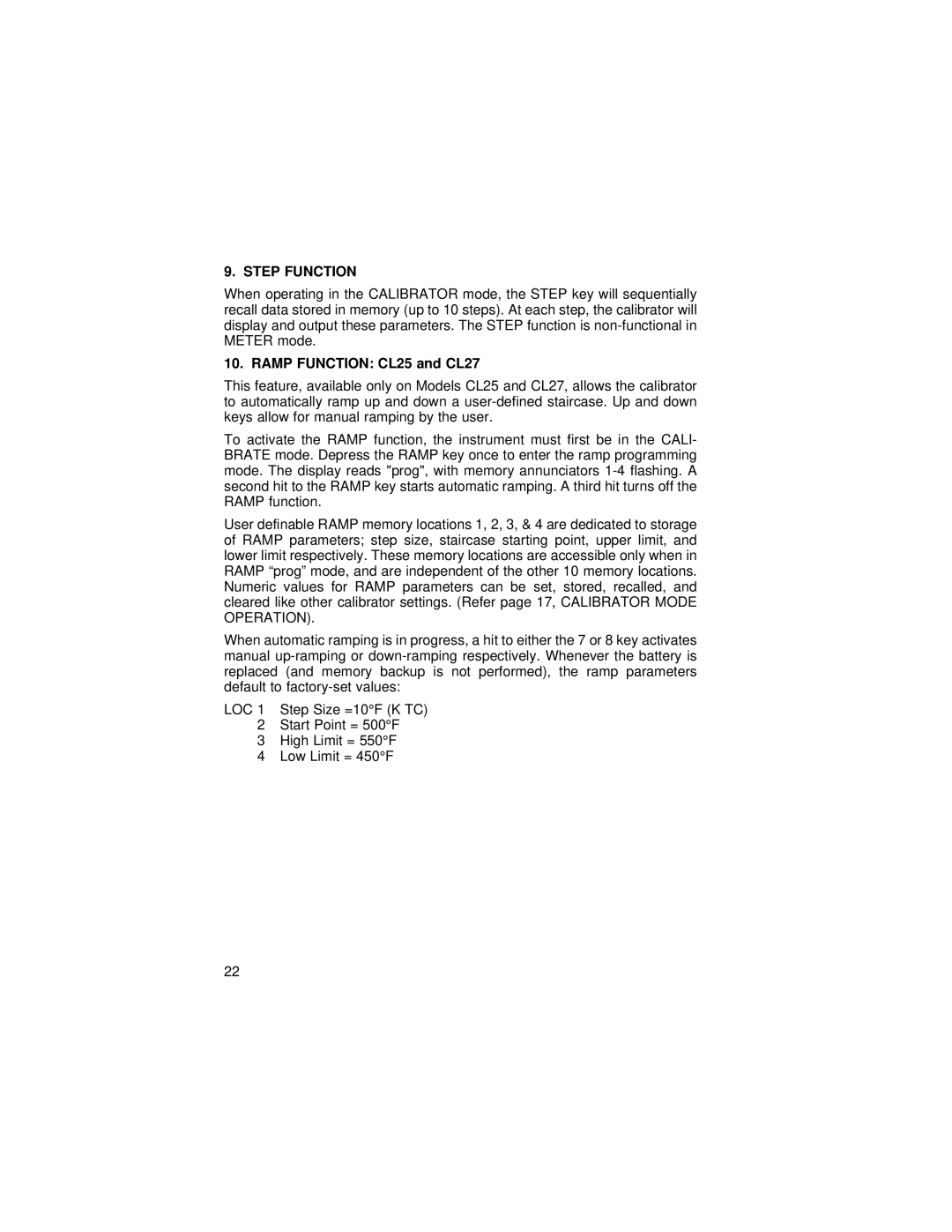
9. STEP FUNCTION

When operating in the CALIBRATOR mode, the STEP key will sequentially recall data stored in memory (up to 10 steps). At each step, the calibrator will display and output these parameters. The STEP function is non-functional in METER mode.

10. RAMP FUNCTION: CL25 and CL27

This feature, available only on Models CL25 and CL27, allows the calibrator to automatically ramp up and down a user-defined staircase. Up and down keys allow for manual ramping by the user.

To activate the RAMP function, the instrument must first be in the CALI- BRATE mode. Depress the RAMP key once to enter the ramp programming mode. The display reads "prog", with memory annunciators 1-4 flashing. A second hit to the RAMP key starts automatic ramping. A third hit turns off the RAMP function.

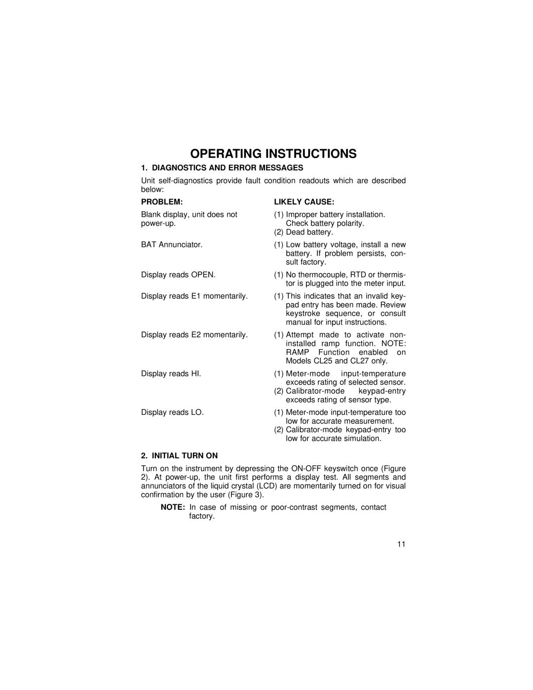
User definable RAMP memory locations 1, 2, 3, & 4 are dedicated to storage of RAMP parameters; step size, staircase starting point, upper limit, and lower limit respectively. These memory locations are accessible only when in RAMP “prog” mode, and are independent of the other 10 memory locations. Numeric values for RAMP parameters can be set, stored, recalled, and cleared like other calibrator settings. (Refer page 17, CALIBRATOR MODE OPERATION).

When automatic ramping is in progress, a hit to either the 7 or 8 key activates manual up-ramping or down-ramping respectively. Whenever the battery is replaced (and memory backup is not performed), the ramp parameters default to factory-set values:

LOC 1 Step Size =10°F (K TC)

LOC 2 Start Point = 500°F

LOC 3 High Limit = 550°F

LOC 4 Low Limit = 450°F

22
Image 24
Contents CL23A, 24, 25, 26 Omega.comTM Table of Contents Common Specifications General InformationTemperature Coefficient Page Unique Specifications Model CL23A/CL23ECModel CL24 Model CL25/CL25ECFeatures Manual AddendaModel CL27/CL27EC Safety Information Safety PrecautionsUnpacking Your Unit Page Battery INSTALLATION/REPLACEMENT Battery InstallationMemory Backup Operation with Rechargeable BatteryDiagnostics and Error Messages Problem Likely CauseOperating Instructions Initial Turn onKeypad Meter Mode Operation Thermocouples Set-Up OPRMeter Mode Operation RTD, Thermistor & Ohms Set-Up HoldData Logging and Recall To Save Readings To Recall ReadingsTo Erase Data Locations Meter Mode Calibrator Mode Operation Thermocouples Set-UpCalibrator Mode Operation RTD, Thermistor & Ohms Set-Up CHANGE/ENTER, 2, 1, 2, 0, CHANGE/ENTERWire Resistance Simulation Storage and Recall of Calibrator Settings To Store OutputsTo Erase Set-Up Locations Calibrator Mode To Recall OutputsStep Function Ramp Function CL25 and CL27Service Information Calibration ProceduresThermocouple Calibration Test Equipment Required Ambient ConditionsPage Calibration Adjustments Meter-Mode Zero & Gain Adjustments Sensor Step Input Adjust ReadingCalibrator-Mode Zero & Gain Adjustments Sensor Output Adjust ReadingCalibration Setup, Copper Mode Resistance Calibration Test Equipment RequiredResistance Calibration Setup Calibration Adjustments Output Input Adjust Verify Reading Input Adjust Verify ReadingCalibration of Meter-Mode Resistance Functions RTD-Thermistor Sensor Unit StepCalibration Verification Model Software Revision Equipment RequiredPage Page Alloy Mode Verification Procedure for Thermocouple Functions Page Mechanical Parts Diagram Calibration Procedures Page Page Page Page Page USAWARRANTY/DISCLAIMER Temperature