


![]() AIR VANTAGE® 500 CUMMINS
AIR VANTAGE® 500 CUMMINS
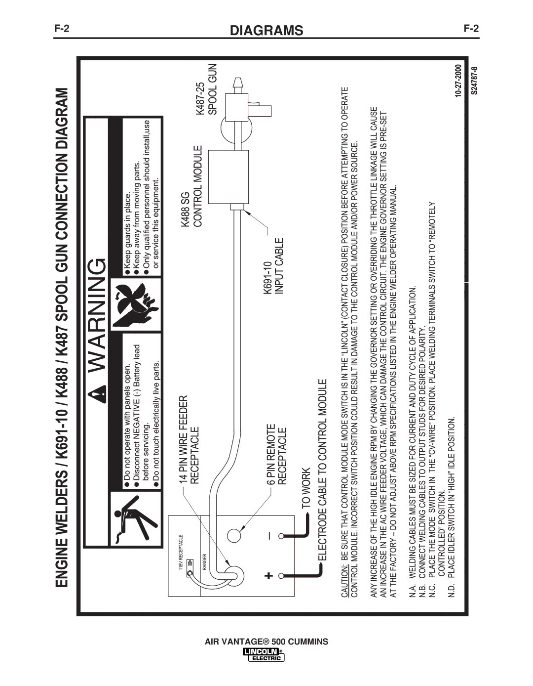
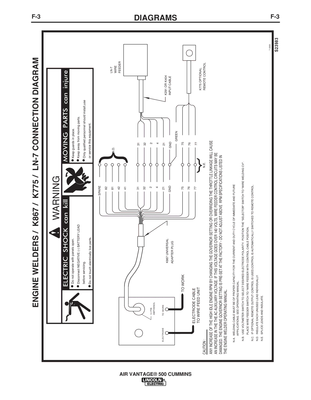
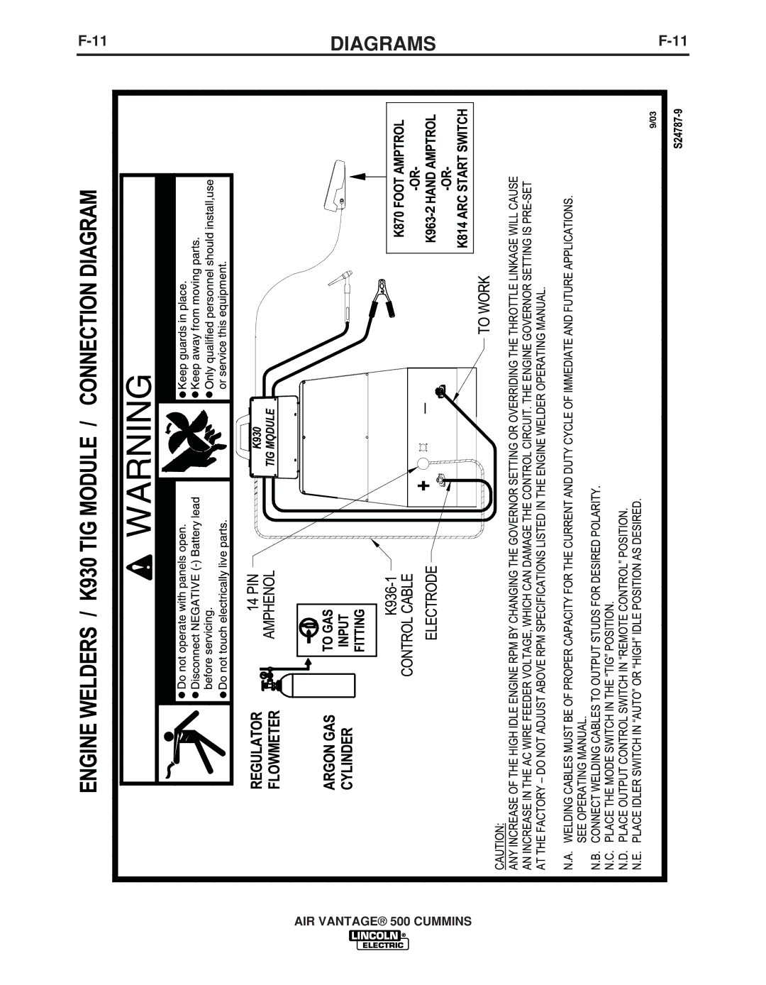
ENGINE WELDERS / K867 / K775 / LN-7 CONNECTION DIAGRAM
|
| WARNING |
|
|
|
|
| Do not operate with panels open. |
| Keep guards in place. |
| ||
| Disconnect NEGATIVE |
| Keep away from moving parts. |
| ||
| before servicing. |
| Only qualified personnel should install,use |
| ||
| Do not touch electrically live parts. |
| or service this equipment. |
| ||
|
| SPARE | } |
|
|
|
|
| 82 |
|
|
| |
|
| 81 | N.D. | |||
|
| 42 |
|
| WIRE | |
|
|
|
| FEEDER | ||
|
| 41 |
|
|
|
|
|
| 31 |
|
| 31 |
|
|
| 32 |
|
| 32 |
|
| 14 PIN | 2 |
|
| 2 |
|
| AMPHENOL | 4 |
|
| 4 |
|
|
|
|
|
| ||
ELECTRODE | TO WORK | 21 |
|
| 21 | K291 OR K404 |
| K867 UNIVERSAL | GND |
|
|
| |
|
|
| GND | INPUT CABLE | ||
| ADAPTER PLUG |
|
| |||
|
|
|
| GREEN |
| |
|
|
|
|
|
| |
| TO WORK | 75 |
|
| 75 |
|
| ELECTRODE CABLE | 76 |
|
| 76 |
|
| 77 |
|
| 77 |
| |
| TO WIRE FEED UNIT | } | K775 OPTIONAL | |||
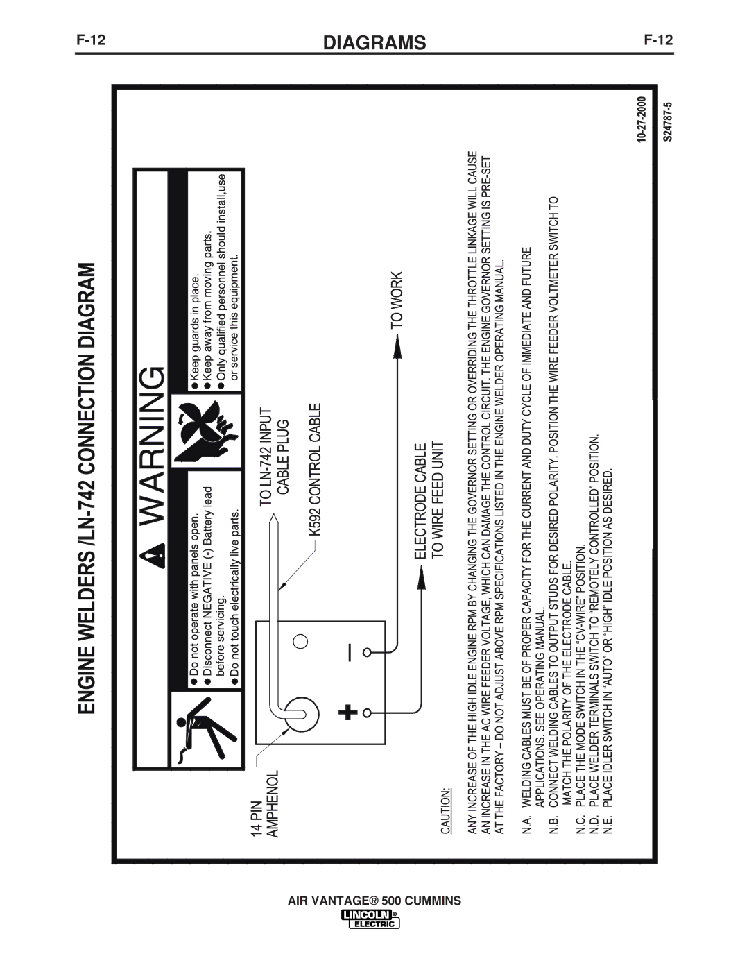
CAUTION : |
|
| ||||
|
| N.E. |
|
| REMOTE CONTROL | |
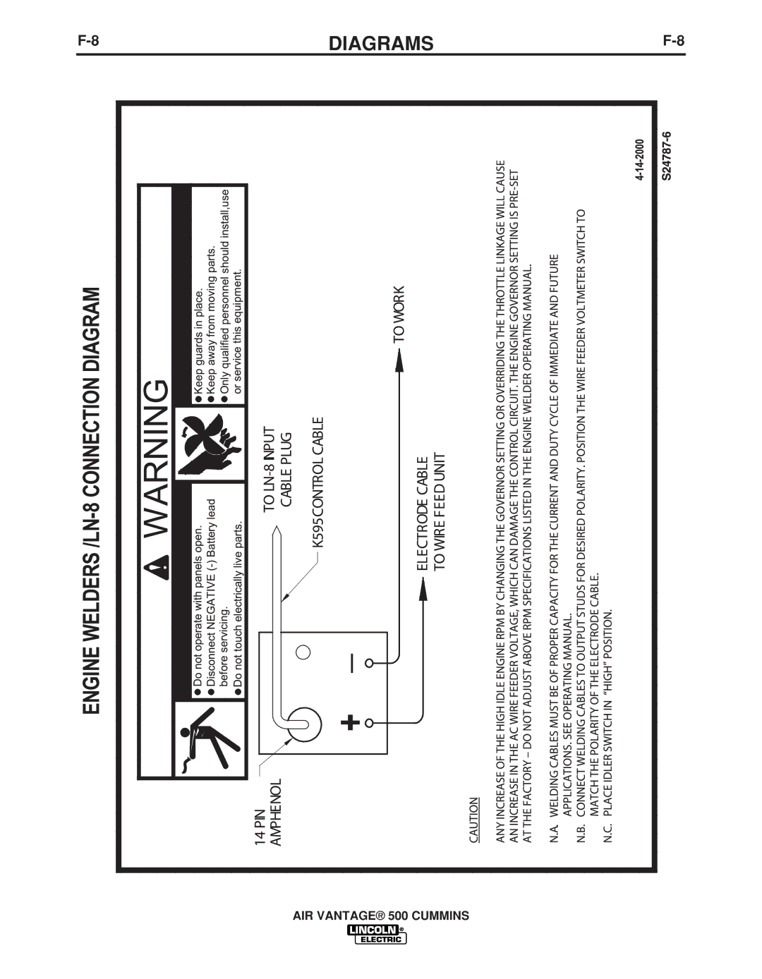
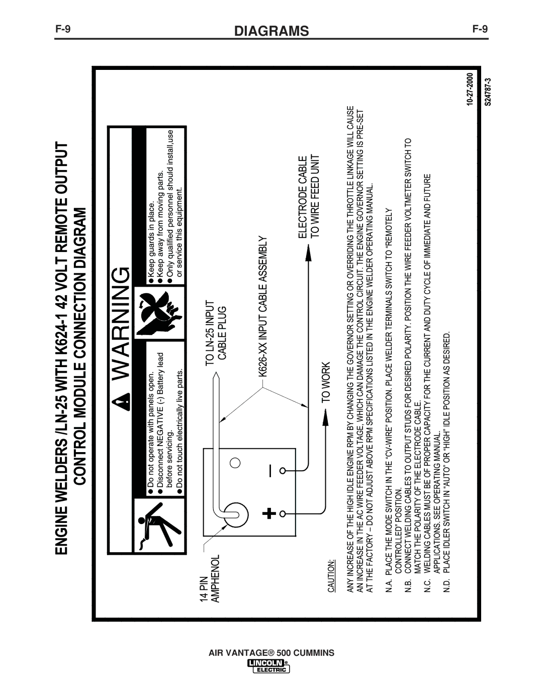
ANY INCREASE OF THE HIGH IDLE ENGINE RPM BY CHANGING THE GOVERNOR SETTING OR OVERRIDING THE THROTTLE LINKAGE WILL CAUSE
AN INCREASE IN THE THE AC AUXILIARY VOLTAGE. IF THIS VOLTAGE GOES OVER 140 VOLTS, WIRE FEEDER CONTROL CIRCUITS MAY BE
DAMAGED. THE ENGINE GOVERNOR SETTING IS
THE ENGINE WELDER OPERATING MANUAL.
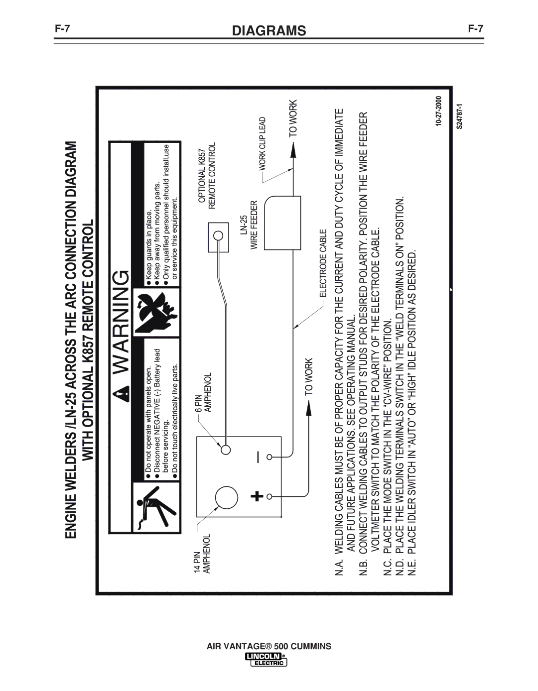
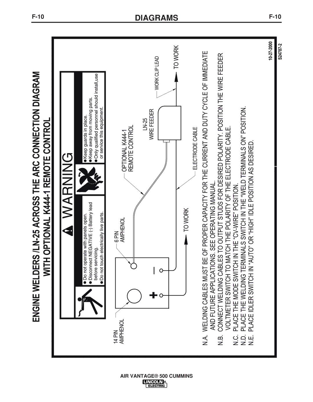
N.A. WELDING CABLE MUST BE OF PROPER CAPACITY FOR THE CURRENT AND DUTY CYCLE OF IMMEDIATE AND FUTURE
APPILICATIONS. SEE OPERATING MANUAL.
N.B. USE VOLTMETER SWITCH TO SELECT DESIRED ELECTRODE POLARITY. POSITION THE "SELECTOR" SWITCH TO "WIRE WELDING CV".
PLACE WIRE FEEDER SWITCH TO "WIRE FEEDER WITH CONTROL CABLE POSITION.
N.C. IF OPTIONAL REMOTE OUTPUT CONTROL IS USED,CONTROL IS AUTOMATICALLY SWITCHED TO REMOTE CONTROL.
N.D. INSULATE EACH UNUSED LEAD INDIVIDUALLY.
N.E. SPLICE LEADS AND INSULATE.
S23983