90538674 PC600D Drill 10/1/08 9:24 AM Page 6
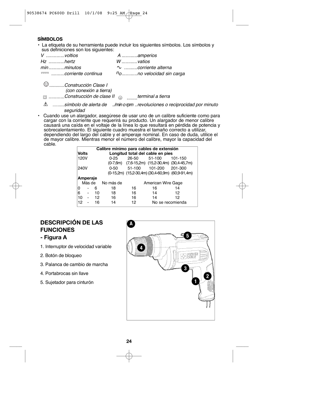
SAFETY WARNINGS AND INSTRUCTIONS: DRILLS
![]()
![]()
![]()
![]()
![]()
![]()
![]()
![]() : Drill may stall (if overloaded or improperly used) causing a twist. Always expect the stall. Grip the drill firmly with both hands to control the twisting action and prevent loss of control which could cause personal injury. If a stall does occur, release the trigger immediately and determine the reason for the stall before
: Drill may stall (if overloaded or improperly used) causing a twist. Always expect the stall. Grip the drill firmly with both hands to control the twisting action and prevent loss of control which could cause personal injury. If a stall does occur, release the trigger immediately and determine the reason for the stall before
ASSEMBLY
![]()
![]()
![]()
![]()
![]()
![]()
![]()
![]() : To reduce the risk of injury, before assembly, make sure that the tool is
: To reduce the risk of injury, before assembly, make sure that the tool is
switched off and unplugged.
INSERTING A DRILL BIT OR OTHER ACCESSORY (FIGURE B)
: Do not attempt to tighten drill bits (or any other accessory) by
gripping the front part of the chuck and turning the tool on. Damage to the chuck
and personal injury may occur when changing accessories.
![]()
![]()
![]()
![]()
![]()
![]()
![]()
![]() : Always ensure the bit is secure before starting the tool. A loose bit
: Always ensure the bit is secure before starting the tool. A loose bit
may eject from tool causing possible personal injury.
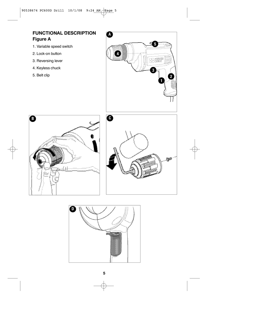
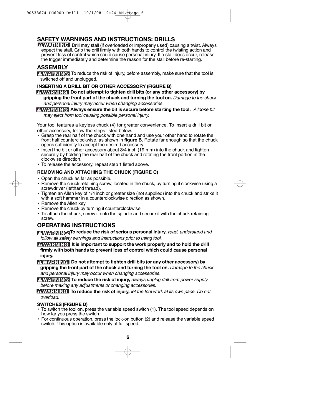
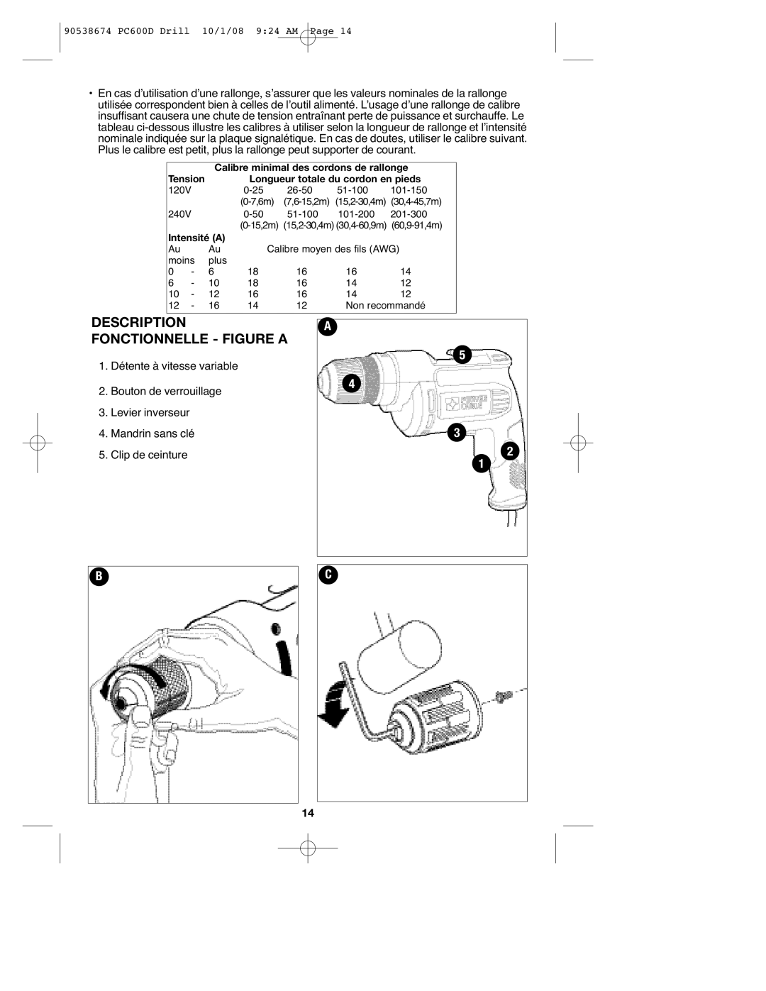
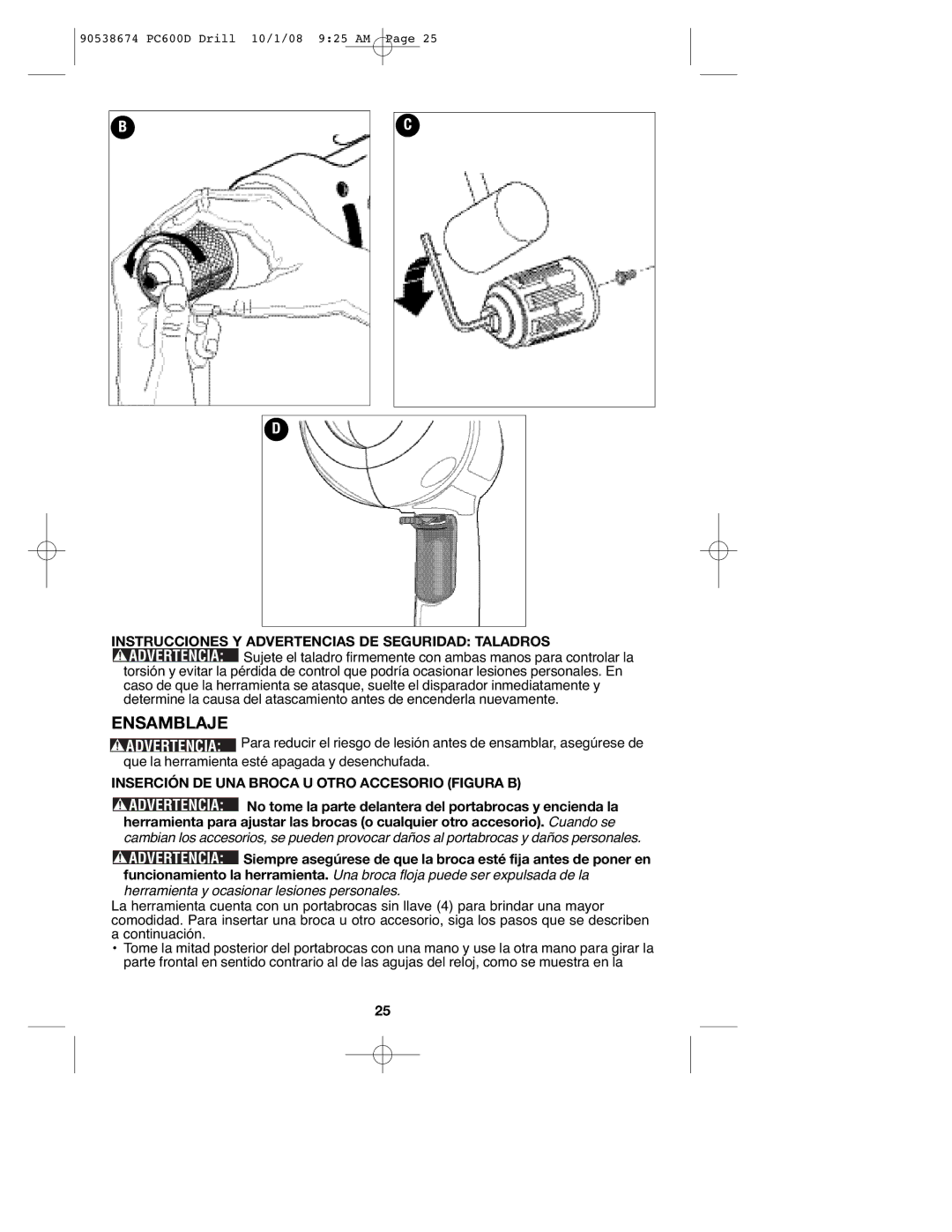
Your tool features a keyless chuck (4) for greater convenience. To insert a drill bit or other accessory, follow the steps listed below.
•Grasp the rear half of the chuck with one hand and use your other hand to rotate the front half counterclockwise, as shown in figure B. Rotate far enough so that the chuck opens sufficiently to accept the desired accessory.
•Insert the bit or other accessory about 3/4 inch (19 mm) into the chuck and tighten securely by holding the rear half of the chuck and rotating the front portion in the clockwise direction.
•To release the accessory, repeat step 1 listed above.
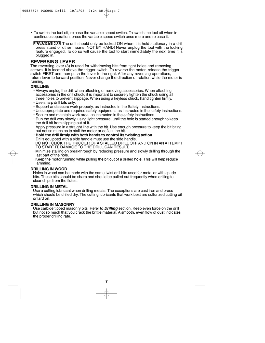
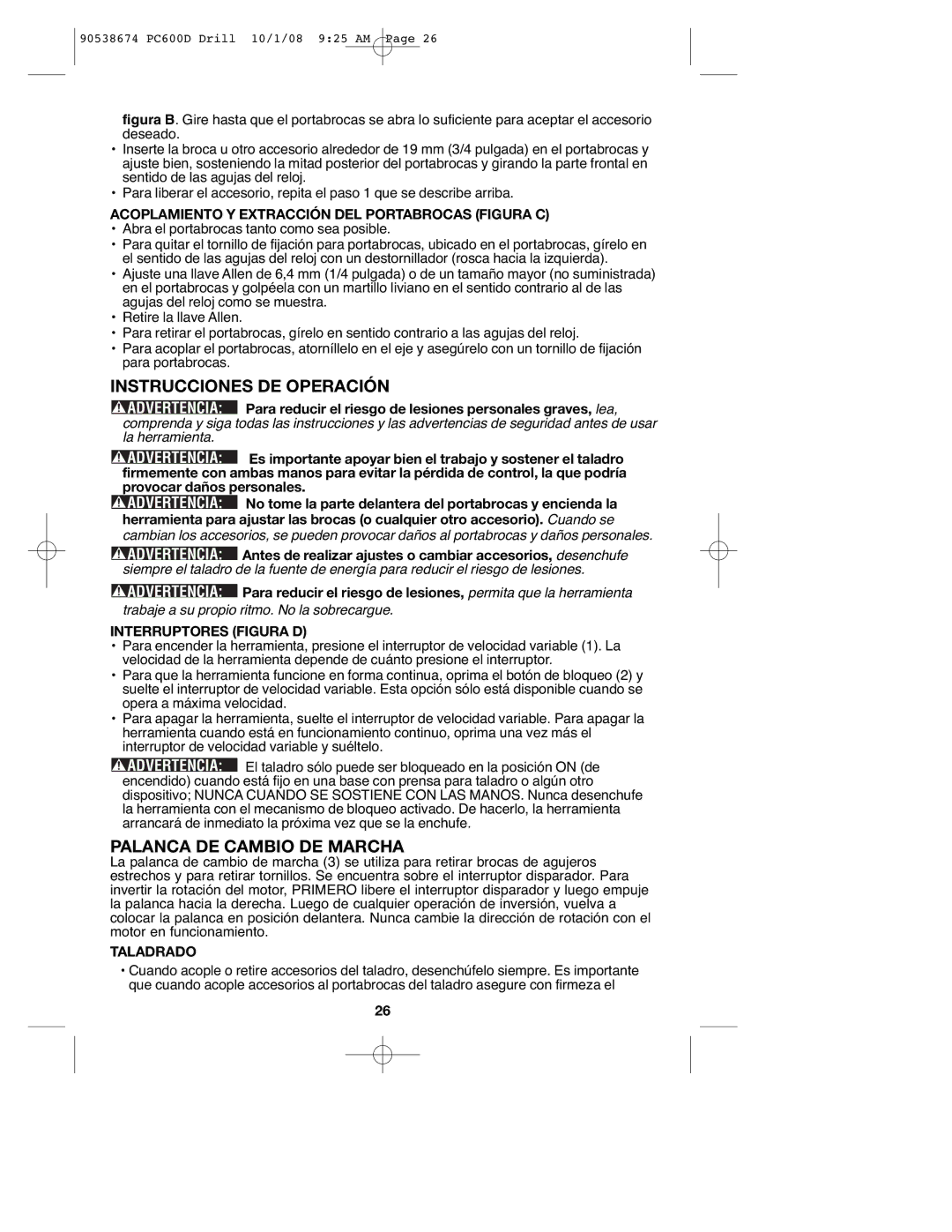
REMOVING AND ATTACHING THE CHUCK (FIGURE C)
•Open the chuck as far as possible.
•Remove the chuck retaining screw, located in the chuck, by turning it clockwise using a screwdriver (lefthand thread).
•Tighten an Allen key of 1/4 inch or greater size (not supplied) into the chuck and strike it with a soft hammer in a counterclockwise direction as shown.
•Remove the Allen key.
•Remove the chuck by turning it counterclockwise.
•To attach the chuck, screw it onto the spindle and secure it with the chuck retaining screw.
OPERATING INSTRUCTIONS
![]()
![]()
![]()
![]()
![]()
![]()
![]()
![]() : To reduce the risk of serious personal injury, read, understand and
: To reduce the risk of serious personal injury, read, understand and
follow all safety warnings and instructions prior to using tool.
![]()
![]()
![]()
![]()
![]()
![]()
![]()
![]() : It is important to support the work properly and to hold the drill
: It is important to support the work properly and to hold the drill
firmly with both hands to prevent loss of control which could cause personal injury.
![]()
![]()
![]()
![]()
![]()
![]()
![]()
![]() : Do not attempt to tighten drill bits (or any other accessory) by gripping the front part of the chuck and turning the tool on. Damage to the chuck
: Do not attempt to tighten drill bits (or any other accessory) by gripping the front part of the chuck and turning the tool on. Damage to the chuck
and personal injury may occur when changing accessories.
![]()
![]()
![]()
![]()
![]()
![]()
![]()
![]() : To reduce the risk of injury, always unplug drill from power supply
: To reduce the risk of injury, always unplug drill from power supply
before making any adjustments or changing accessories.
![]()
![]()
![]()
![]()
![]()
![]()
![]()
![]() : To reduce the risk of injury, let the tool work at its own pace. Do not
: To reduce the risk of injury, let the tool work at its own pace. Do not
overload.
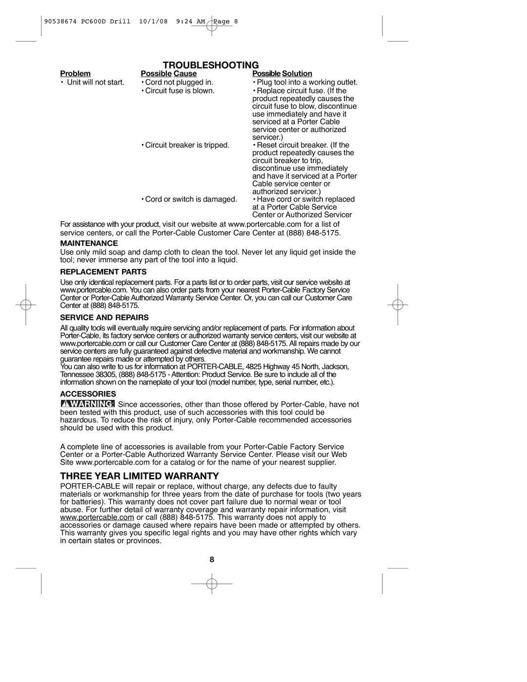
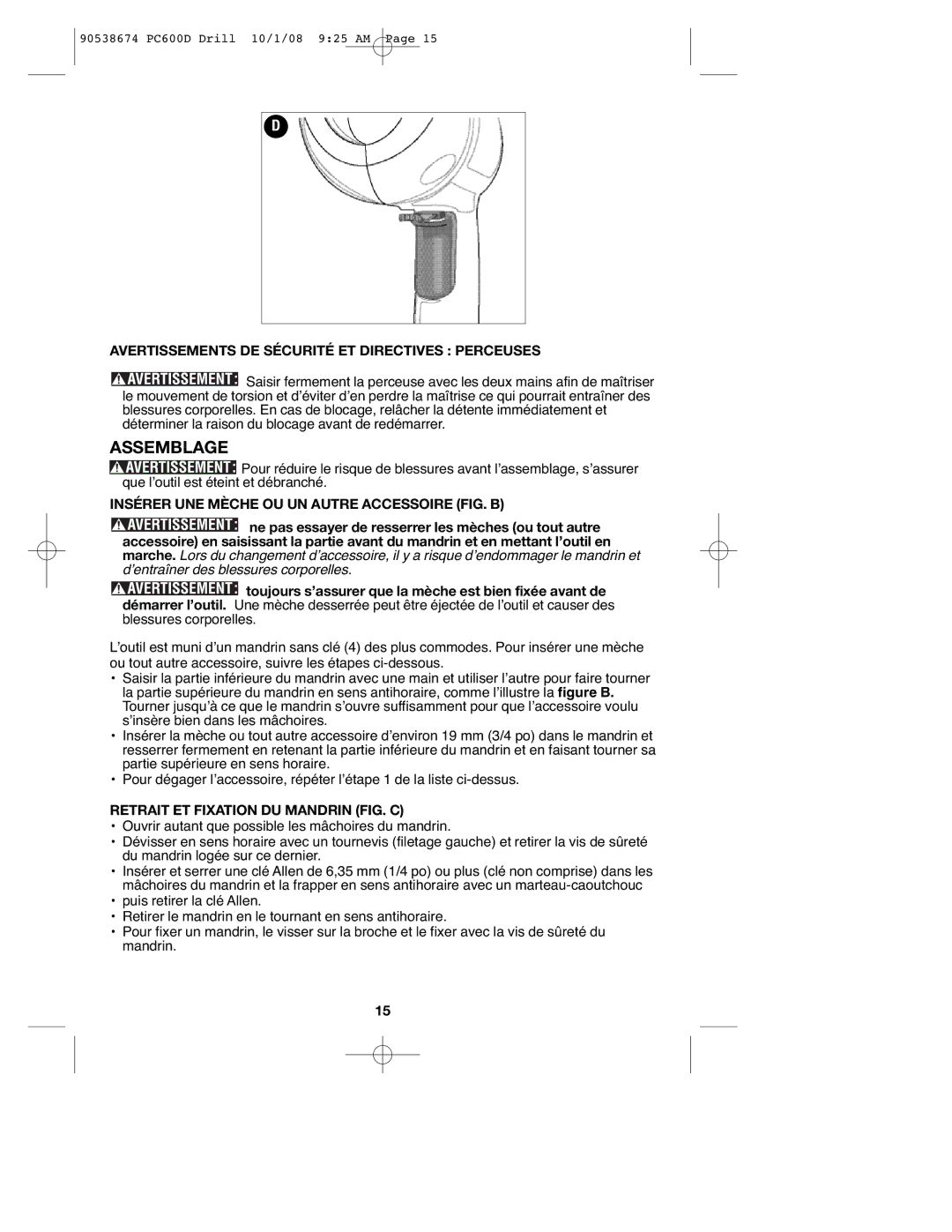
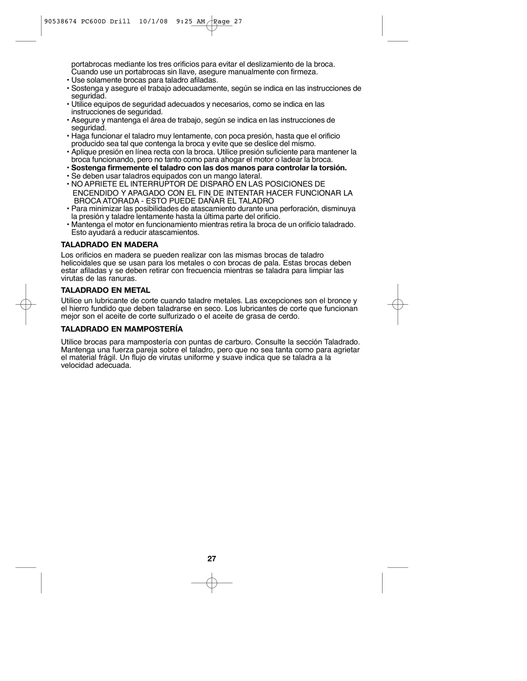
SWITCHES (FIGURE D)
•To switch the tool on, press the variable speed switch (1). The tool speed depends on how far you press the switch.
•For continuous operation, press the
6
