DeWalt 36-714 instruction manual Power Connections, Motor Specifications, Grounding Instructions

Page 5

POWER CONNECTIONS

A separate electrical circuit should be used for your machines. This circuit should not be less than #12 wire and should be protected with a 20 Amp time lag fuse. If an extension cord is used, use only 3-wire extension cords which have 3-prong grounding type plugs and matching receptacle which will accept the machine’s plug. Before connecting the machine to the power line, make sure the switch (s) is in the “OFF” position and be sure that the electric current is of the same characteristics as indicated on the machine. All line connections should make good contact. Running on low voltage will damage the machine.

Do not expose the machine to rain or operate the machine in damp locations.

MOTOR SPECIFICATIONS

Your machine is wired for 120/240 Volt,60 HZ alternating current. Before connecting the machine to the power source, make sure the switch is in the “OFF” position.

GROUNDING INSTRUCTIONS

This machine must be grounded while in use to protect the operator from electric shock.

1.All grounded, cord-connected machines:

In the event of a malfunction or breakdown, grounding provides a path of least resistance for electric current to reduce the risk of electric shock. This machine is equipped with an electric cord having an equipment-grounding conductor and a grounding plug. The plug must be plugged into a matching outlet that is properly installed and grounded in accordance with all local codes and ordinances.

Do not modify the plug provided - if it will not fit the outlet, have the proper outlet installed by a qualified electrician.

Improper connection of the equipment-grounding conduc-tor can result in risk of electric shock. The conductor with insulation having an outer surface that is green with or without yellow stripes is the equipment-grounding conductor. If repair or replacement of the electric cord or plug is necessary, do not connect the equipment- grounding conductor to a live terminal.

Check with a qualified electrician or service personnel if the grounding instructions are not completely understood, or if in doubt as to whether the machine is properly grounded.

Use only 3-wire extension cords that have 3-prong grounding type plugs and matching 3-conductor receptacles that accept the machine’s plug, as shown in Fig. A.

Repair or replace damaged or worn cord immediately.

2.Grounded, cord-connected machines intended for use on a supply circuit having a nominal rating less than 150 volts:

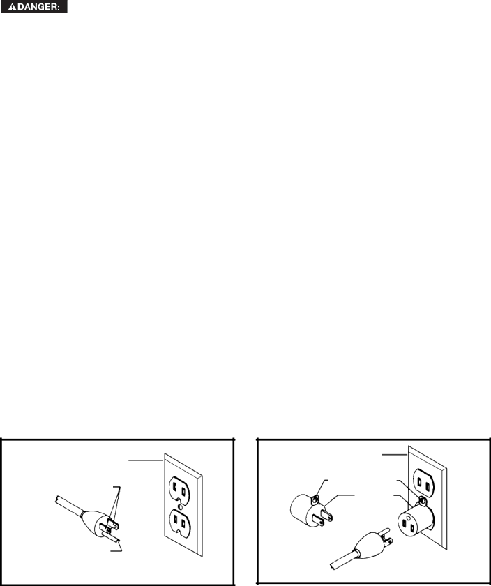
If the machine is intended for use on a circuit that has an outlet that looks like the one illustrated in Fig. A, the machine will have a grounding plug that looks like the plug illustrated in Fig. A. A temporary adapter, which looks like the adapter illustrated in Fig. B, may be used to connect this plug to a matching 2-conductor receptacle as shown in Fig. B if a properly grounded outlet is not available. The temporary adapter should be used only until a properly grounded outlet can be installed by a qualified electrician. The green-colored rigid ear, lug, and the like, extending from the adapter must be connected to a permanent ground such as a properly grounded outlet box. Whenever the adapter is used, it must be held in place with a metal screw.

NOTE: In Canada, the use of a temporary adapter is not permitted by the Canadian Electric Code.

In all cases, make certain that the receptacle in question is properly grounded. If you are not sure, have a qualified electrician check the receptacle.

GROUNDED OUTLET BOX

CURRENT

CARRYING

PRONGS

GROUNDED OUTLET BOX

GROUNDING MEANS

ADAPTER

GROUNDING BLADE

IS LONGEST OF THE 3 BLADES

5

Image 5
Contents Hybrid Saw Safety Guidelines Definitions Table of Contents Important Safety Instructions General Safety Rules Do not CUT Metal with this SAW Additional Specific Safety RulesGrounding Instructions Power ConnectionsMotor Specifications Minimum Gauge Extension Cord Volt Single Phase OperationExtension Cords Functional Description Carton ContentsUnpacking and Cleaning AssemblyInstalling the Drive Belt Extension Wings Installing the SwitchRouting the Cord Attaching the Blade Guard and Splitter AssemblyAdjusting the Table Insert Aligning the Splitter with the Blade Installing Table InsertAttaching a SAW Blade Installing the Tool Holders Adjusting Table InsertInstalling Dust Port Assembling the Miter GaugeAdjusting 90 and 45 Positive Stops Locking the Switch in the OFF PositionOperation Starting and Stopping the SAWAligning the Miter Slots to the Blade Quick Operations Checklist Miter Gauge Operation and AdjustmentCROSS-CUTTING Splitter Assembly and AlignmentBlade Guard and Splitter USE Ripping MiteringBevel Crosscutting Compound MiteringConstructing a Push Stick Bevel Ripping Using a Moulding CutterheadMust Using AN Accessory Dado HeadConstructing a Featherboard Power Tool InstituteUsing Auxiliary Wood Facing Constructing a Push Stick Push StickService Troubleshooting MaintenanceKeep Machine Clean Lubrication & Rust ProtectionWarranty AccessoriesLA Proposition DE Californie LES Instructions Importantes DE SureteMesures DE Sécurité Définitions Lutilisation DE CET Outil Règles DE Sécurité GénéralesConserver CES Directives Règles Spécifiques Additionnelles DE SûretéInstructions DE Mise À LA Terre Raccordements ÉlectriquesSpécifications DU Moteur Mesur Minimum DE Corde D’EXTENSION Cordon DE RallongeFonctionnement Monophasé À 240 Volts AVANT-PROPOS Description FonctionnelleContenus DE Boite Désemballage ET Nettoyage AssemblageFixation DE LA Scie À UN Endroit Permanent Volants DE Réglage DE LA LameInstallation DE LA Courroie Dentraînement Rallonges Installation DE LinterrupteurFixation DE Lensemble PROTÈGE-LAME/COUTEAU Séparateur Acheminement DU CordonPage Alignement DU Couteau Séparateur Avec LA Lame Installation DE Linsert DE TableFixation DE LA Lame DE LA Scie Réglage DE L’INSERT DE LA Table Installation DES PORTE-OUTILSInstallation DE LA Goulotte À Poussière Démarrage ET Arrêt DE LE Scie FonctionnementVerrouiller L’INTERRUPTEUR EN Position D’ARRÊT Protection Contre LES SurchargesAlignement DES Fentes DE LA Jauge À Onglet Avec LA Lame Liste DE Contrôle Rapide Avant Utilisation Fonctionnement ET Réglage DE LA Jauge À OngletET Alignement DU PARE-MAIN ET DU Couteau Séparateur » Utilisation DU PARE-MAIN ET DU Couteau SéparateurTronçonnage EN Biseau Découpe À L’ONGLETDécoupe À Onglet Mixte Sciage EN Long« Fabrication D’UN Poussoir » Tenir LES Mains Éloignées DE LA Lame DE ScieUtilisation DE LA Fraise À Moulurer Sciage SUR LE Long EN BiseauUtilisation DE LA Tête À Rainurer Accessoire Utilisation D’UNE Planche DE Repère Fabrication D’UNE Planche EN Éventail Construire UN Poussoir PoussoirDepannage Entretien Remplacement Gratuit DE LétiquettePièces DE Rechange Entretien ET RéparationGarantie AccessoiriesGuarde Estas Instrucciones Instrucciones DE Seguridad ImportantesPautas DE SEGURIDAD/DEFINICIONES EL USO DE Esta Herramienta Normas Generales DE SeguridadNo Corte Metal CON Esta Sierra Normas Específicas Adicionales DE SeguridadInstrucciones DE Conexión a Tierra Conexiones a LA Fuente DE AlimentaciónEspecificaciones DEL Motor Operación DE UNA Sola Fase CON 240 Voltios Cordones DE ExtensiónCordón DE Extensión DE Calibre Mínimo Prologo Descripción FuncionalContenido DE Carton Estimación DEL Tiempo DE Ensamblaje EnsamblajeInstalación DE LA Correa Impulsora Instalación DEL Interruptor Bases DE ExtensiónAcople DEL Conjunto Protector DE LA Hoja Y Hendedor Recorrido DEL CablePage Instalación DEL Inserto DE Mesa Acople DE HojaAlineación DEL Hendedor CON LA Hoja Instalación DEL Orificio Para Recolección DE Polvo Ajuste DEL Inserto DE MesaArrancando Y Deteniendo LA Sierra OperaciónFijando EL Interruptor EN LA Posicion DE Apagado Protección DE SobrecargaAlineación DE LAS Ranuras DEL Calibrador CON LA Hoja Lista Decontrol DE Operaciones Rápidas Operación Y Ajuste DEL Calibrador DE IngleteAlineación DEL Protector DE LA Hoja Y EL Hendedor USO DEL Protector DE LA Hoja Y DEL HendedorCorte Transversal Corte Transversal CON Bisel Corte a IngleteCorte Longitudinal Corte CON Ingletes CompuestosMantenga LAS Manos Lejos DE LA Hoja DE LA Sierra USO DEL Cabezal Portacuchilla Para Moldura Corte Longitudinal CON BiselUSO DEL Inserto DE Cabezal Para Ranuras Construcción DE UNA Tabla DE Canto Biselado Construcción DE UNA Tabla DE Canto Biselado Menorque 4ODEUNESPESOR Elanchodelmaterial AcortarConstrucción DE UNA Vara Para Empujar Utilice Madera DE 12,7 MM 1/2Servicio Localizacion DE Fallas MantenimientoGarantia AccesoriosNotas Delta Machinery Highway 45 North Jackson, TN 800