Heat & Glo LifeStyle XLR-PB-CE, XLR-N-CE Installing Vent Pipe SLP Pipe, Assemble Vent Sections

Page 35

10 Installing Vent Pipe (SLP Pipe)

A. Assemble Vent Sections

To attach the first vent component to the starting collars of the appliance:

Lock the vent components into place by sliding the pipe section onto the collar.

Align the seam of the pipe and seam of collar to allow engagement. Rotate the vent component to lock into place. Use this procedure for all vent components. See Figure 10.1.

• Slide the gasket over the first vent section and place it flush to the appliance. This will prevent cold air infiltration. High temperature caulk (150 ºC minimum continuous exposure rating) may be used to hold the part in place.

Continue adding vent components, locking each succeeding component into place.

Ensure that each succeeding vent component is securely fitted and locked into the preceding component.

Commercial, Multi-family (Multi-level exceeding two sto- ries), or High-Rise Applications

For Installation into a commercial, multi-family (multi-level exceeding two stories) or high-rise applications: All outer

pipe joints must be sealed with high temperature (150 ºC minimum continuous exposure rating) silicone, including the slip section that connects directly to the horizontal ter- mination cap.
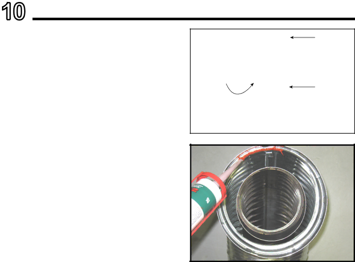
Apply a bead of silicone sealant inside the female outer pipe joint prior to joining sections. See Figure 10.2

Only outer pipes need to be sealed. All unit collar, pipe, slip section, elbow and cap outer flues shall be sealed in this manner, unless otherwise stated.

WARNING! Risk of Fire or Explosion! DO NOT break silicone seals on slip sections. Use care when removing termination cap from slip pipe. If slip section seals are bro- ken during removal of the termination cap, vent may leak.

Note: Align seams to engage pipe, then rotate counterclockwise to lock

Figure 10.1 Adding Venting Components

Figure 10.2 High Temperature Silicone Sealant (300ºF minimum continuous exposure rating)

Heat & Glo • XLR-N-CE, XLR-PB-CE2198-900 Rev. J • 5/12

35

Image 35
Contents What to do if you smell gas EC-87/09/058Homeowner Reference Information CongratulationsUser Guide Table of ContentsReference Materials Appliance SetupTroubleshooting Component AccessLimited Lifetime Warranty Limited Lifetime Warranty Hearth & Home Technologies IncWarranty Conditions Limited Lifetime WarrantyListing and Code Approvals Your Fireplace Gas Fireplace SafetyOperating Instructions User Guide Decorative Doors and Fronts Fixed Glass AssemblyRemote Controls, Wall Controls and Wall Switches Clear SpaceControl Module Operation  Nine Hour Safety Shutdown FeatureModule Reset Switch AGE 110/120 VAC or 220/240 Lighting Instructions IPIFinal inspection by After Fireplace is Lit Battery Tray/Battery InstallationFrequently Asked Questions Initial Break-in ProcedureDecorative Doors Maintenance and ServiceMaintenance Tasks-Homeowner Glass CleaningControl Compartment and Firebox Top Maintenance Tasks-Qualified Service TechnicianGasket Seal and Glass Assembly Inspection FireboxTypical Appliance System Getting StartedInspect Appliance and Components Design and Installation ConsiderationsTools and Supplies Needed Selecting Appliance Location Framing and ClearancesConstructing the Appliance Chase Clearances Minimum Framing DimensionsMantel Leg Combustible/Non-Combustible Mantel and Wall ProjectionsMantels Combustible/Non-Combustible Vent Termination Minimum Clearances Termination LocationsCovered Alcove Applications Vent Information and Diagrams Minimum Maximum Top Vent Horizontal Termination Venting with 1 elbowTop Vent Horizontal Termination Venting with 2 elbows Exhaust restrictor Instructions Top Vent Vertical Termination No Elbows V1 = 13,4 mV1 Minimum Maximum V1 + V2 Minimum Top Vent Vertical Termination Venting with 2 elbowsV1 Minimum H1 + H2 Maximum V1 + V2 Minimum Top Vent Vertical Termination Venting with 3 elbowsMin Max Top Vent Vertical Termination Venting with 4 elbowsCombustible Wall Penetration Vent Clearances and FramingPipe Clearances to Combustibles Wall Penetration FramingPipe SLP Install the Ceiling FirestopVaulted Ceiling Installation Install Attic Insulation ShieldFlat Ceiling Installation Top Vent Appliance PreparationProper Positioning, Leveling And Securing of an Securing and Leveling the ApplianceAssemble Vent Sections Installing Vent Pipe SLP PipeSecure The Vent Sections Assemble Slip SectionsDisassemble Vent Sections Install Decorative Ceiling ComponentsAssemble and Install Storm Collar Install Metal Roof FlashingHeat Shield Requirements for Horizontal Termination Install Vertical Termination CapInstall Decorative Wall Components 17 Venting through the wall Install Horizontal Termination CapGas Pressure Requirements Gas Connection Access Through the Valve AssemblyGas Information Optional Remote Control Receiver and Battery Pack Location Wiring RequirementsIntelliFire Plus Ignition System Wiring Optional Accessories RequirementsJunction Cord Information Electrical Service and Repair BlowerFinishing Instructions Non-Combustible Materials SpecificationFinishing Framing and Finishing InstructionsFACTORY-INST Alled Wallboard Joint-Crack Prevention and Repair Finish and Sealing JointsFinishing Around Opening with Gypsum Wallboard PaintingOverlap Fit Method Tonic or Martini Decorative Front Facing MaterialNon-Combustible Finish Material 0-10 cm Thick Decorative Fronts Dimensions of Tonic Decorative FrontAppliance Setup Media Options Air Shutter SettingAir Shutter Settings IntelliFire Plus Ignition System TroubleshootingSymptom Possible Cause Corrective Action Ues to spark, and main Component Access Valve Assembly Gasket Pilot Assembly Replacement Gas Valve ReplacementReference Materials Appliance Dimension DiagramVent Components Diagrams Ceiling Firestop SLP-45 45 ElbowSLP90- 90 Elbow Extended Heat ShieldBlack 30,5 cm 17,8 cm 39,4 cm SnorkelSupport Box-Black AdapterSLP-HRC-SS SLP-HRC-ZC-SS Horizontal Termination CAP Landscape DV Appliance Service Parts#14 Valve Assembly XLR-N-CE, XLR-PB-CE Service Parts ListContact Information