Burnham MMII manual VI. Venting / Air Intake Piping, Component, General Guidelines

Page 11

VI. Venting / Air Intake Piping

NOTICE

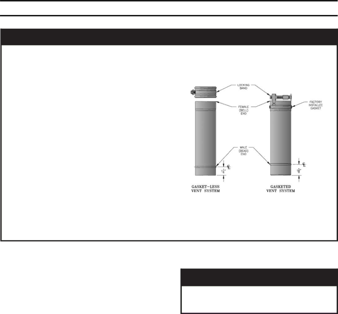
The gasketed vent system components pictured below in Figure A are being phased in and each vent component is interchangeable with the previously supplied gasket-less venting components. The newer vent components are generally quicker and easier to join, as they do not require the sealant application and their clamp bands are attached.

In the event a gasketed vent component and a gasket-less vent component must be intercon- nected, follow the instructions associated with Figure 10B or 10C. The two guiding principles of these instructions are as follows:

1) Any joining of vent components that involves at least one gasket-less vent component always requires the sealant application.

2) The female end of a gasket-less


vent component always requires


a clamp band, regardless of the


design of the mating male vent

Figure A: Burnham Vent

component.

Each gasket-less vent component is supplied with a clamp band and sealant.

A Vent Transition Kit, part number 6116302, is available that contains one clamp band and one 3 ounce tube of sealant.

A.General Guidelines.

1.Vent system installation must be in accordance with National Fuel Gas Code, ANSI Z223.1, Venting of Equipment, or applicable provisions of local building codes. Contact local building or fire officials about restrictions and installation inspection in your area.

2.This appliance requires a Special Gas Vent. The product is designed to use Burnham supplied

AL 29-4C®Stainless Steel vent system components. The following manufacturer's offer similar AL 29- 4C® components and are approved for use with this product: Heat-Fab Inc. - Saf-T-Vent, Flex-L International Inc. - Star-34, Protech Systems, Inc. - FasNSeal™, and Z-Flex U. S., Inc. - Z-Vent. The use of these alternate manufacturer's venting systems will require adapters to connect to the Burnham supplied vent connector and vent terminal. These adapters are not supplied with this unit and should be obtained from the supplier of the alternate manufacturer's venting system. See Table 7 for complete parts list.

WARNING

Do not use this boiler with galvaniz ed, 304 or 316 stainless steel or any other non AL29-4C®based vent systems.

3.Vent length restrictions are based on equivalent length of vent pipe (total length of straight pipe plus equivalent length of fittings). Maximum vent length is listed in Table 6. Do not exceed maximum vent/ air intake lengths. Table 7 lists equivalent length for fittings. Do not include Vent Terminal or Vent Connector in equivalent feet calculation.

Table 6: Vent/Air Intake Length

3" Vent Pipe (Equiv. Ft.)

4" Air Intake Pipe (Equiv. Ft.)


Min.

Max.

Min.

Max.


8

70

8

70


11

Image 11
Contents 81404025R13-1/07 Price $3.00 MinutemanTable of Contents Dimensional Drawing Minimum Clearances to Combustible Surfaces Pre-InstallationDo not drop boiler. Do not bump boiler jacket against floor II. Unpack BoilerIII. Water Piping and Trim Page Internal Water Piping System Diagram Domestic Hot Water Ratings IV. Domestic Hot Water Performance and PipingRated Input Gas PipingSpecific Gravity Correction Factors Fitting Equivalent LengthsVent/Air Intake Length VI. Venting / Air Intake PipingComponent General GuidelinesBurnham Vent System Components Install Vent ConnectorInstall Vent Pipe, Burnham Gasketed Vent System Install Vent Pipe, GeneralInstall Vent Pipe, Burnham Gasket-Less Vent System Burnham Gasketed Vent Joint Detail Horizontal Through Wall Vent InstallationRecommended Horizontal Vent Installation Horizontal Vent Pipe Wall Penetration Vertical Through Roof Vent InstallationInstall Air Intake Pipe Vertical Vent InstallationVII. Electrical Wiring DiagramPrepare to check operation Do not install an automatic fill valve with this boilerVIII. System Start-up Operating Instructions Check Boiler High Limit Adjust gas input rate to boilerGas Flow Rate in Cubic Feet per Hour IX. Service Lubrication Main Burners and Combustion ChamberBurner and Flueway Cleaning Pilot Burner Location Differential Pressure Switch SettingsAvoid Breathing Fiber Particulates and Dust Page Page Cerafelt Gasketing not depicted Repair PartsHeat Exchanger Assembly Canopy/Blower AssemblyPage Page Base Assembly Page Page Jacket Assembly Domestic Water Tank Assembly Miscellaneous Trim and Controls Air Intake Terminal Vent Accessory CartonLimited Warranty