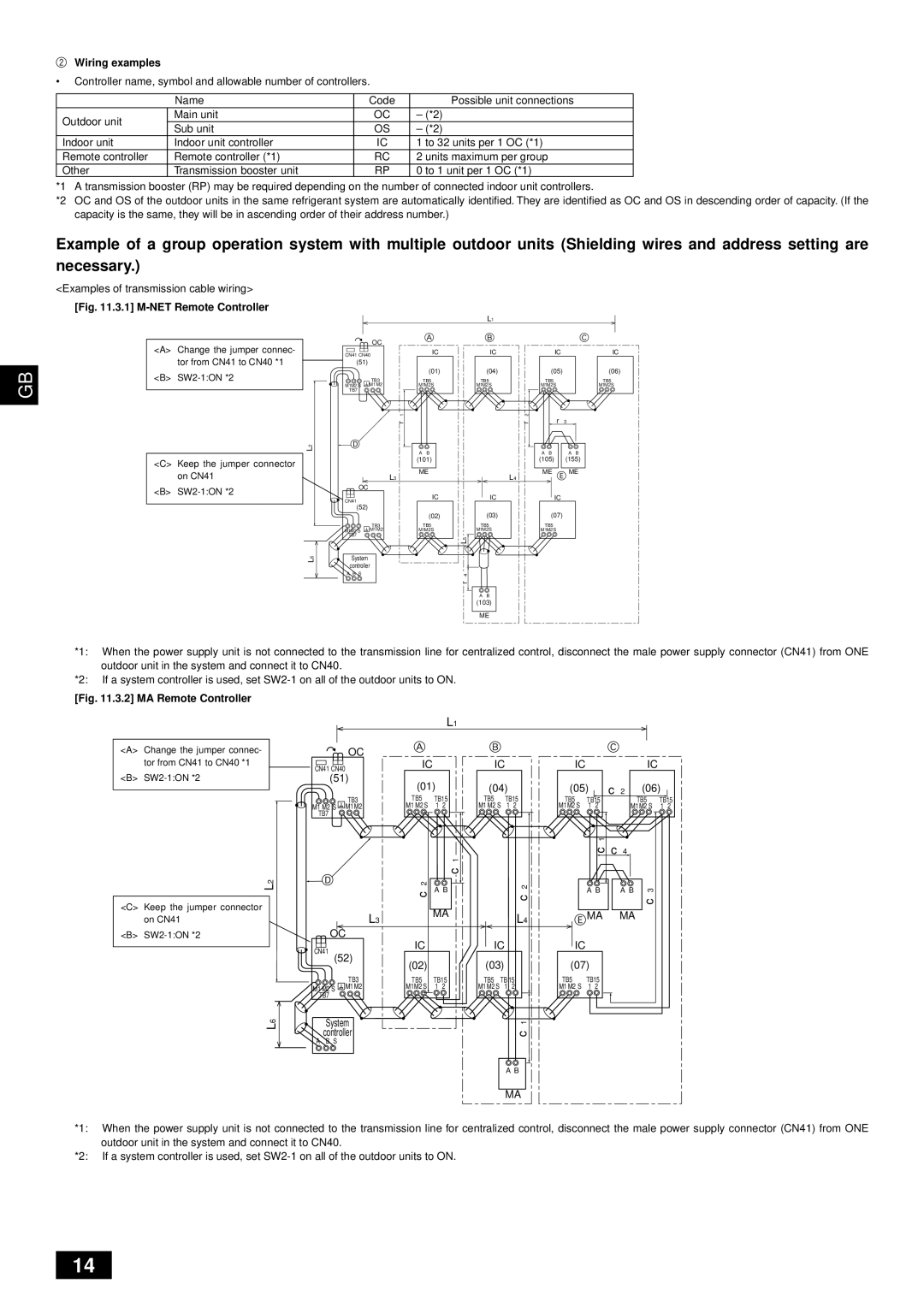
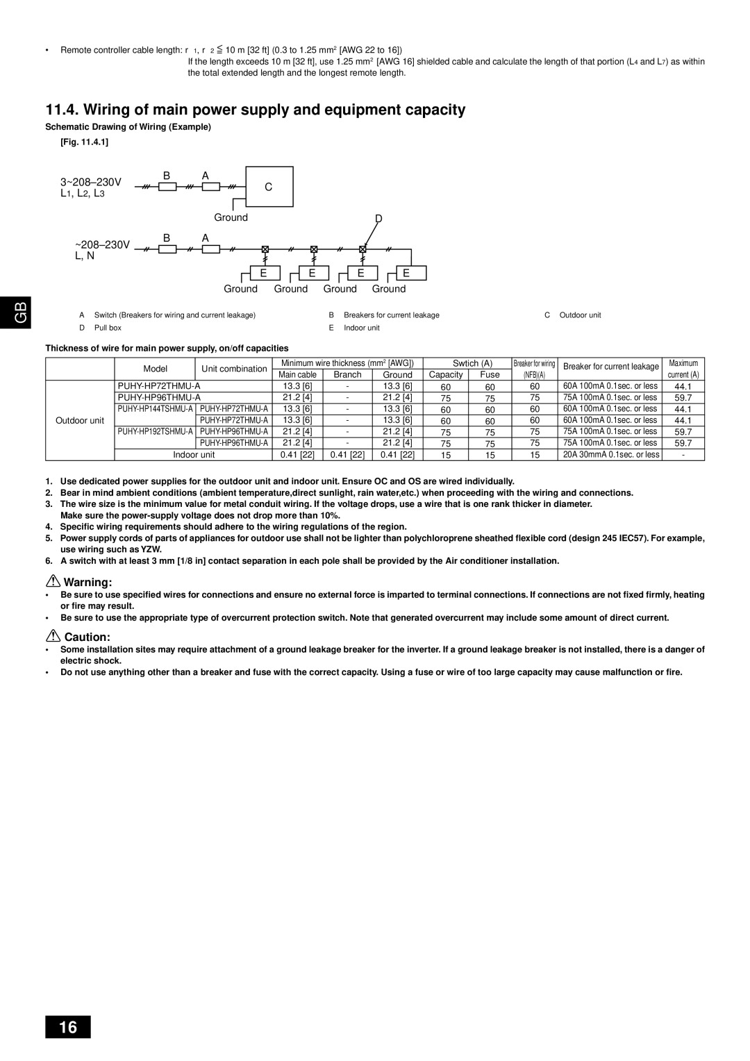
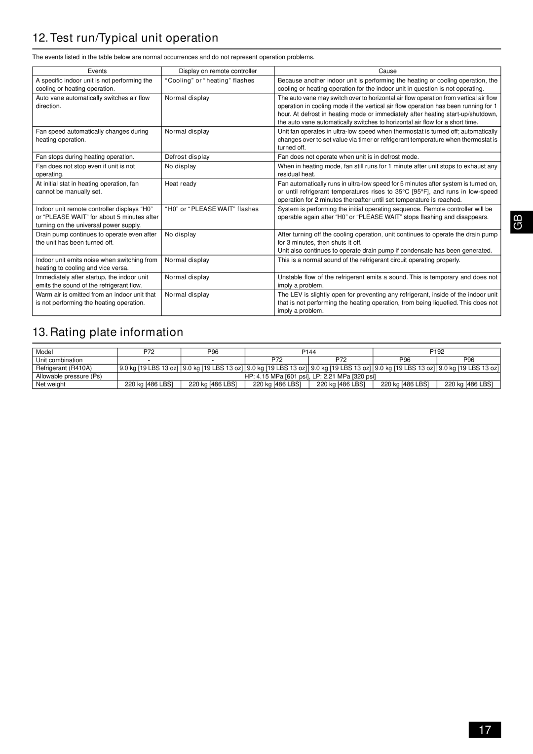
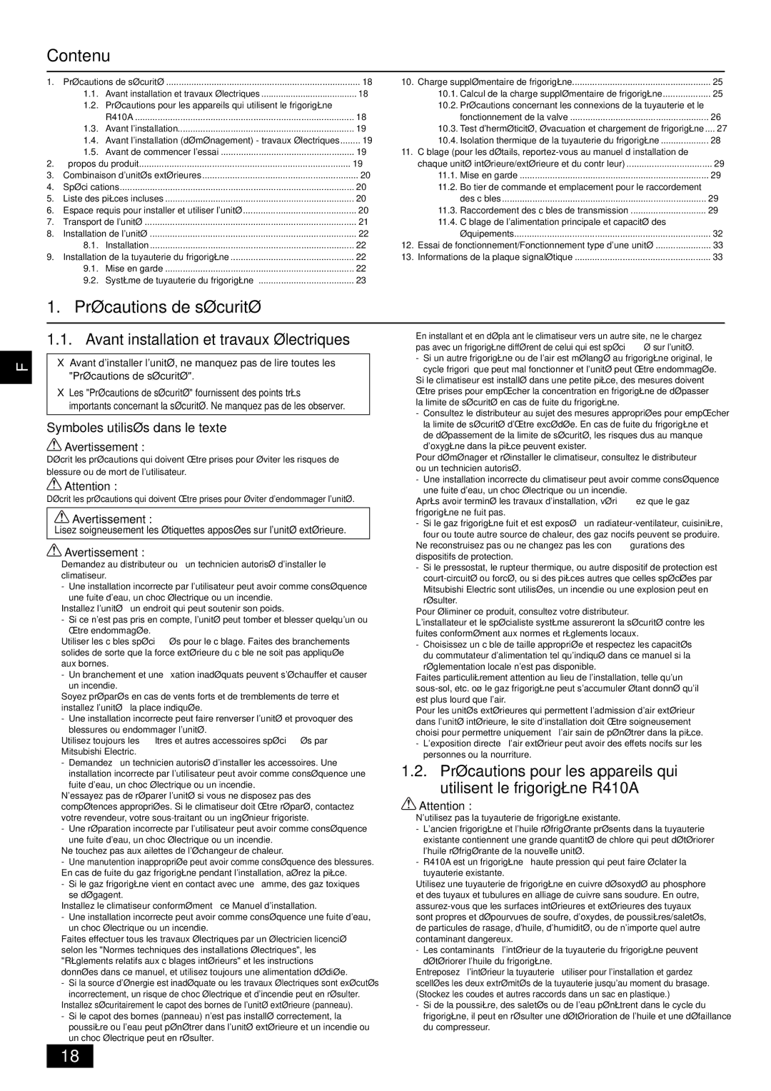
Mitsubishi Electronics PUHY-HP-THMU-A Combination of outdoor unit, Specifications

Page 4

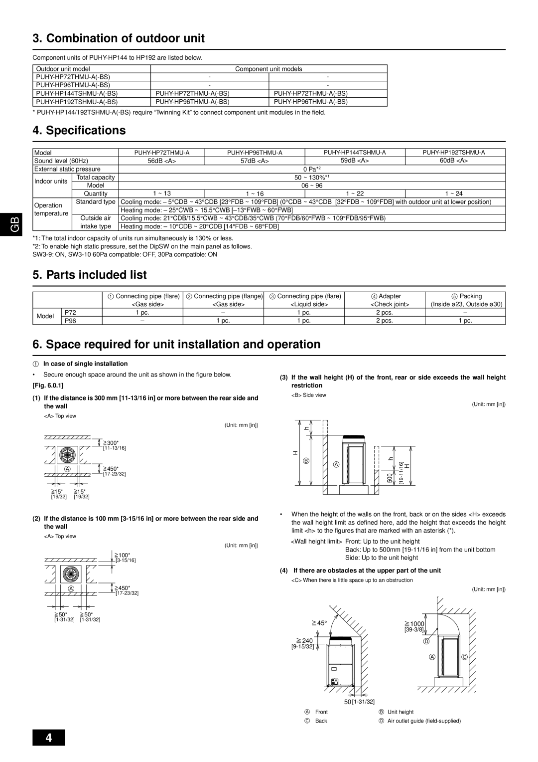
3. Combination of outdoor unit

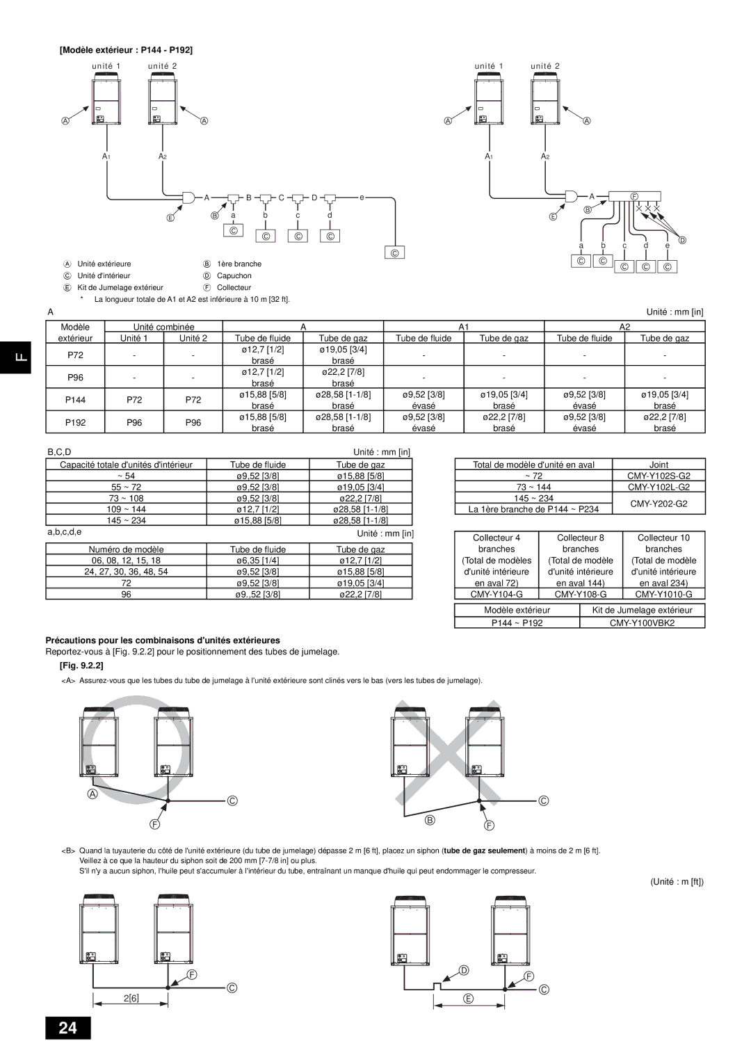
Component units of PUHY-HP144 to HP192 are listed below.

Outdoor unit model


Component unit models

PUHY-HP72THMU-A(-BS)

-


-

PUHY-HP96THMU-A(-BS)

-


-

PUHY-HP144TSHMU-A(-BS)

PUHY-HP72THMU-A(-BS)


PUHY-HP72THMU-A(-BS)

PUHY-HP192TSHMU-A(-BS)

PUHY-HP96THMU-A(-BS)


PUHY-HP96THMU-A(-BS)

* PUHY-HP144/192TSHMU-A(-BS) require “Twinning Kit” to connect component unit modules in the field.

4. Specifications


Model


PUHY-HP72THMU-A

PUHY-HP96THMU-A


PUHY-HP144TSHMU-A


PUHY-HP192TSHMU-A


Sound level (60Hz)

56dB <A>

57dB <A>


59dB <A>


60dB <A>


External static pressure


0 Pa*2


Indoor units


Total capacity


50 ~ 130%*1


Model


06 ~ 96


Quantity

1 ~ 13


1 ~ 16


1 ~ 22


1 ~ 24


Operation


Standard type

Cooling mode: – 5°CDB ~ 43°CDB [23°FDB ~ 109°FDB] (0°CDB ~ 43°CDB [32°FDB ~ 109°FDB] with outdoor unit at lower position)


Heating mode: – 25°CWB ~ 15.5°CWB [–13°FWB ~ 60°FWB]


temperature


GB


Outside air

Cooling mode: 21°CDB/15.5°CWB ~ 43°CDB/35°CWB (70°FDB/60°FWB ~ 109°FDB/95°FWB)


intake type

Heating mode: – 10°CDB ~ 20°CDB [14°FDB ~ 68°FDB]


*1: The total indoor capacity of units run simultaneously is 130% or less.


*2: To enable high static pressure, set the DipSW on the main panel as follows.


SW3-9: ON, SW3-10 60Pa compatible: OFF, 30Pa compatible: ON


5. Parts included list


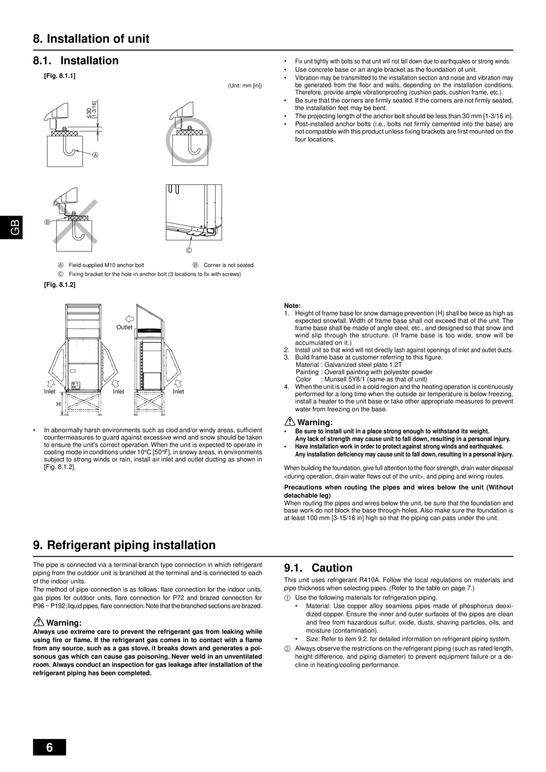
1 Connecting pipe (flare)

2 Connecting pipe (flange)

3 Connecting pipe (flare)


4 Adapter


5 Packing


<Gas side>


<Gas side>


<Liquid side>


<Check joint>


(Inside ø23, Outside ø30)


Model


P72


1 pc.


1 pc.


2 pcs.


P96


1 pc.


1 pc.


2 pcs.


1 pc.


6. Space required for unit installation and operation

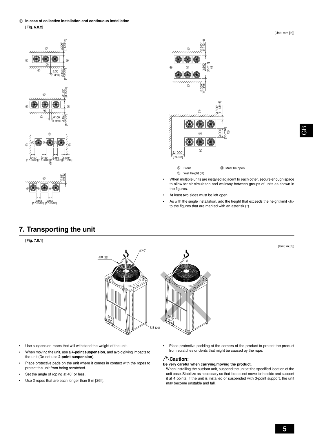
1In case of single installation

Secure enough space around the unit as shown in the figure below.

[Fig. 6.0.1]

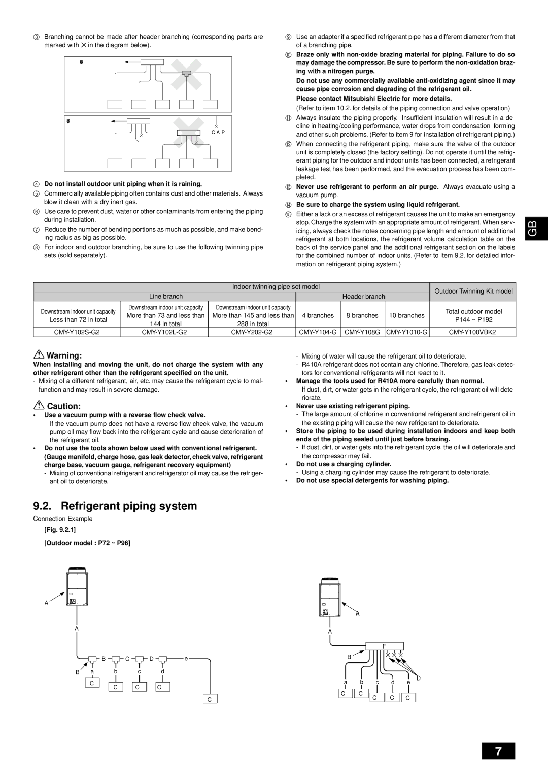
(1)If the distance is 300 mm [11-13/16 in] or more between the rear side and the wall

<A> Top view

(Unit: mm [in])

300*

[11-13/16]

A 450*

[17-23/32]

15* 15*

[19/32] [19/32]

(3)If the wall height (H) of the front, rear or side exceeds the wall height restriction

<B> Side view

(Unit: mm [in])

h


H

h


B

[19-11/16] H

A


500

(2)If the distance is 100 mm [3-15/16 in] or more between the rear side and the wall

<A> Top view

(Unit: mm [in])

100*

[3-15/16]

A 450*

[17-23/32]

50*

50*

[1-31/32] [1-31/32]

When the height of the walls on the front, back or on the sides <H> exceeds the wall height limit as defined here, add the height that exceeds the height limit <h> to the figures that are marked with an asterisk (*).

<Wall height limit> Front: Up to the unit height


Back: Up to 500mm [19-11/16 in] from the unit bottom


Side: Up to the unit height


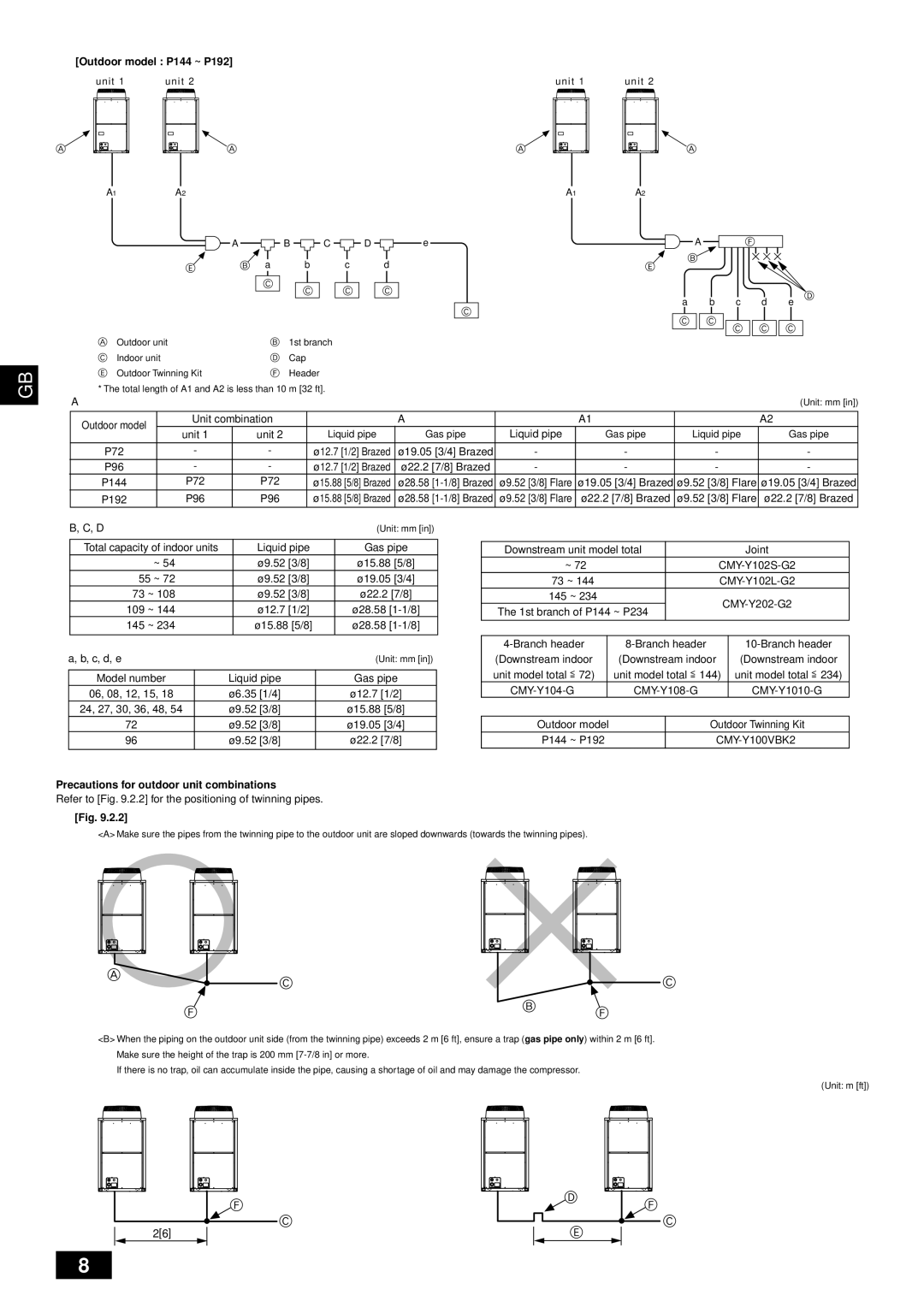
(4) If there are obstacles at the upper part of the unit


<C> When there is little space up to an obstruction


(Unit: mm [in])

45°

1000


[39-3/8]


240

D


[9-15/32]


A

C


50 [1-31/32]

A

Front

B Unit height

C

Back

D Air outlet guide (field-supplied)

4

Image 4
Contents Outdoor Unit Contents Safety precautionsBefore installation Before installation relocation electri- cal workAbout the product Before starting the test runSpecifications Space required for unit installation and operationCombination of outdoor unit Parts included listBe very careful when carrying/moving the product Transporting the unitInstallation of unit Refrigerant piping installationInstallation Outlet Inlet Inlet InletRefrigerant piping system Precautions for outdoor unit combinations Outdoor model P144 ~ P192Additional refrigerant charge Calculation of additional refrigerant chargeAppropriate tightening torque Cap N·m /kg·cm Shaft N·m /kg·cm Size of hexagonalWrench mm Ø9.52 3/8 22/220 Ø12.7 1/2 20/200Airtight test, evacuation, and refrigerant charging Airtight testOnly use refrigerant R410A EvacuationTemperature Resistance Thermal insulation of refrigerant pipingOutdoor Water-proof hemp cloth + Zinc plate + Oily paint Refrigerant ChargingWiring transmission cables Wiring examples Examples of transmission cable wiringUnnecessary address setting Necessary main/sub setting GroundSequence with the IC Main Automatically identified. *1Schematic Drawing of Wiring Example Wiring of main power supply and equipment capacityThickness of wire for main power supply, on/off capacities Test run/Typical unit operation Rating plate informationContenu Avant installation et travaux électriquesPrécautions de sécurité Avant linstallation Avant linstallation déménagement travaux électriquesPropos du produit Avant de commencer lessaiEspace requis pour installer et utiliser lunité Combinaison dunités extérieuresSpécifications Liste des pièces inclusesTransport de lunité En cas dinstallation collective FigFaites très attention en portant/déménageant le produit Installation de lunité Installation de la tuyauterie du frigorigèneInstallation Mise en gardeNutilisez jamais la tuyauterie du frigorigène existante Système de tuyauterie du frigorigèneModèle extérieur P72 P96 Modèle extérieur P144 P192 Précautions pour les combinaisons dunités extérieuresCharge supplémentaire de frigorigène Calcul de la charge supplémentaire de frigorigèneCouple de serrage approprié Test dherméticité Test dherméticité, évacuation et chargement de frigorigèneUtilisez uniquement le frigorigène R410A Du frigorigène Isolation thermique de la tuyauterieChargement du frigorigène Raccordement des câbles de transmission 1 Télécommande M-NET Exemples de câblageÉlévateur du niveau des signaux de transmission ~208-230V L1, L2, L3 Terre ~208-230V L, N Schéma du câblage exemple FigInformations de la plaque signalétique Essai de fonctionnement/Fonctionnement type dune unitéPage Page WT05234X02