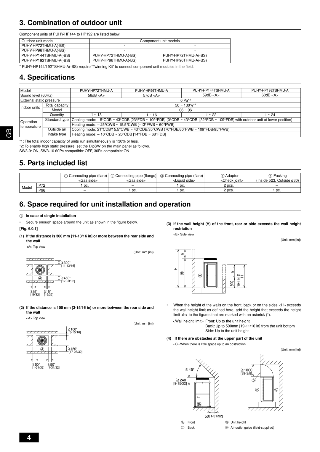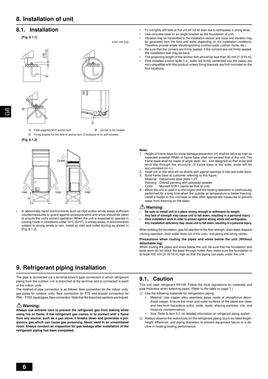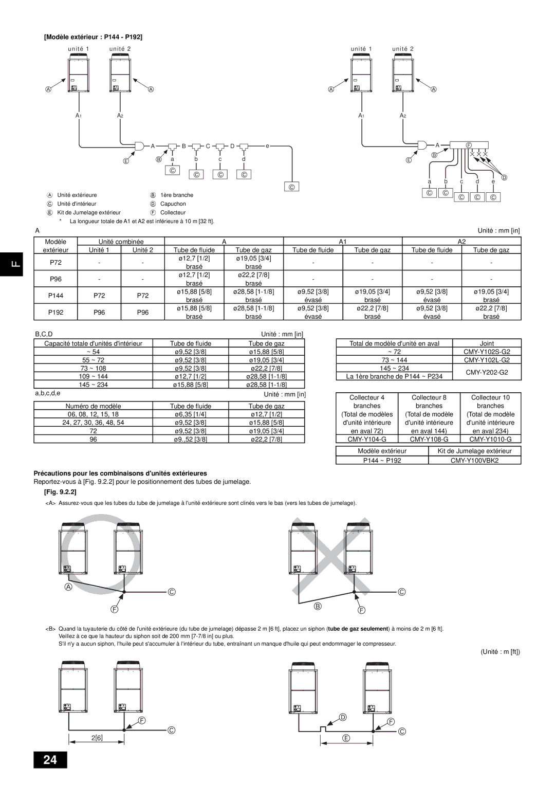
<C>Slope of twinning pipes
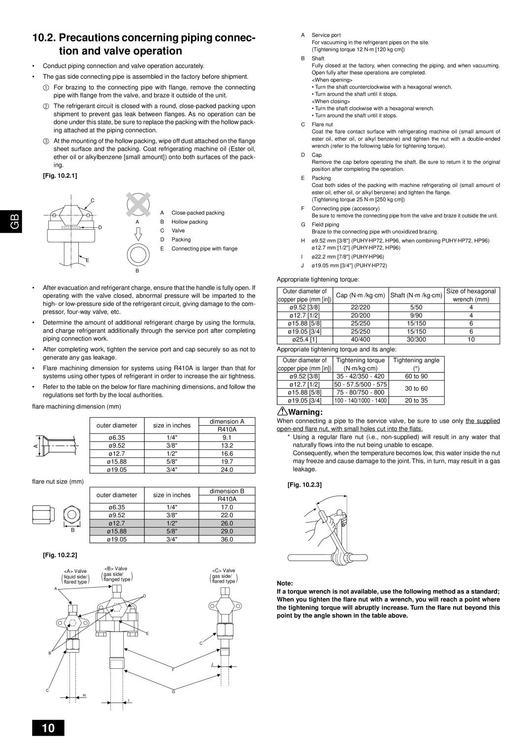
Make sure the slope of the twinning pipes are at an angle within ±15˚ to the ground.
If the slope exceeds the specified angle, the unit may be damaged.
F
±15°
G
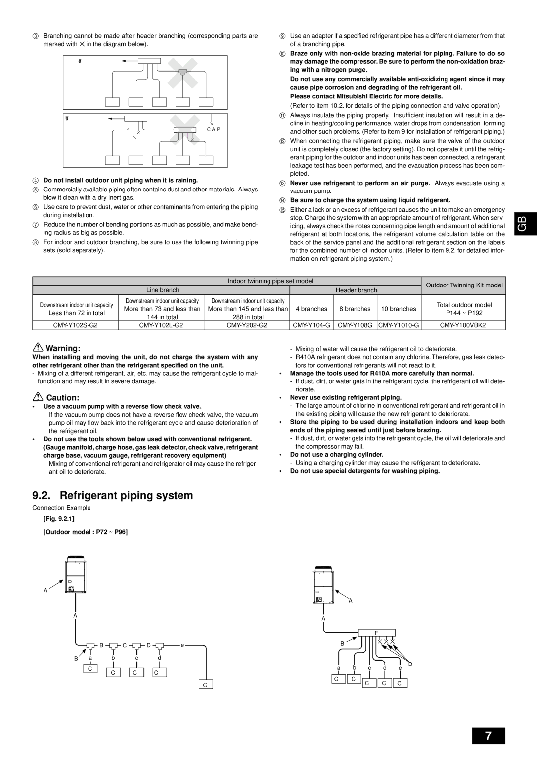
<D>Pipe connection example
GB
H
I
H
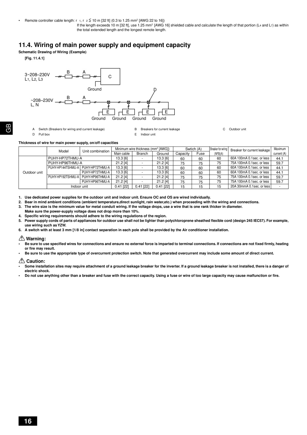
J
A | Downward slope | B | Upward slope | C 1st branch | D Trap (gas pipe only) | E | Within 2 m [6 ft] |
F | Twinning pipe | G Slope of the twinning pipes are at an angle within ±15˚ to the ground | H | Pipes on site | |||
I | Twinning Kit | J | Straight run of pipe that is 500 mm |
|
|
| |
10. Additional refrigerant charge
At the time of shipping, the outdoor unit is charged with refrigerant.
This charge does not include the amount needed for extended piping and additional charging of each refrigerant line will be required on site. In order that future servicing may be properly provided, always keep a record of the size and length of each refrigerant line and the amount of additional charge by writing it in the space provided on the outdoor unit.
10.1.Calculation of additional refrigerant charge
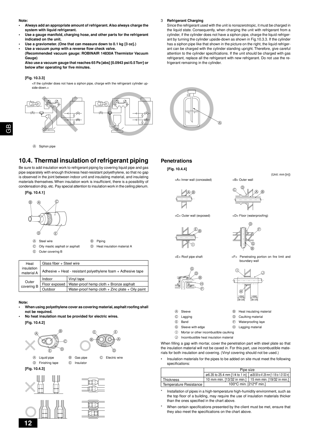
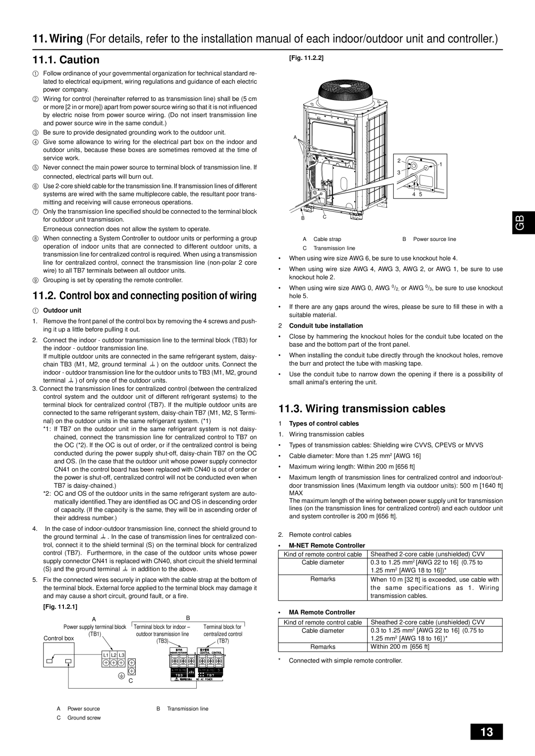
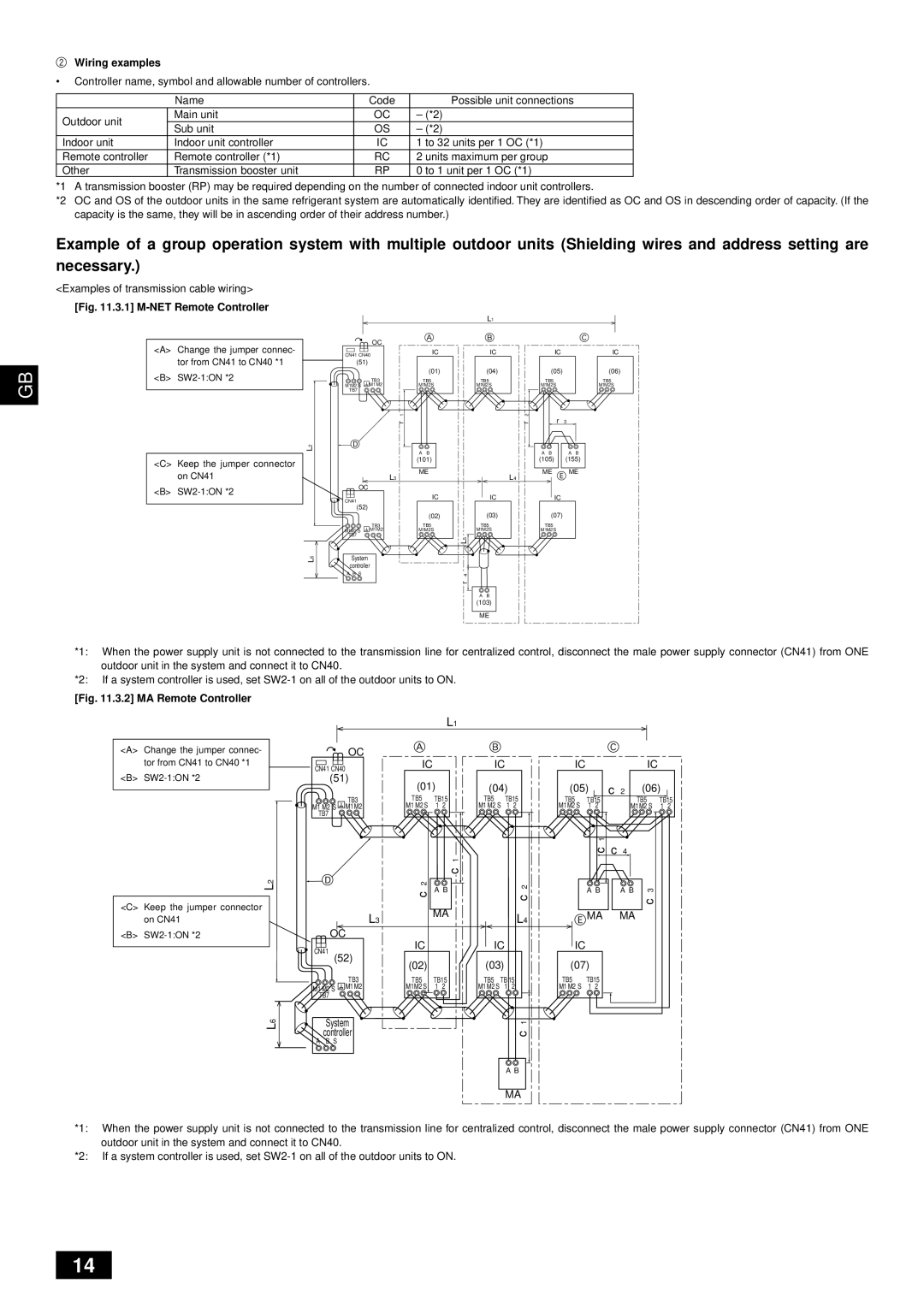
•Calculate the amount of additional charge based on the length of the piping extension and the size of the refrigerant line.
•Use the table below as a guide for calculating the amount of additional charg- ing and then charge the system accordingly.
•If the calculation results in a fraction of less than 0.1 kg [4 oz], round up to the next 0.1 kg [4 oz]. For example, if the result of the calculation was 11.38 kg [402 oz], round the result up to 11.4 kg [404 oz].
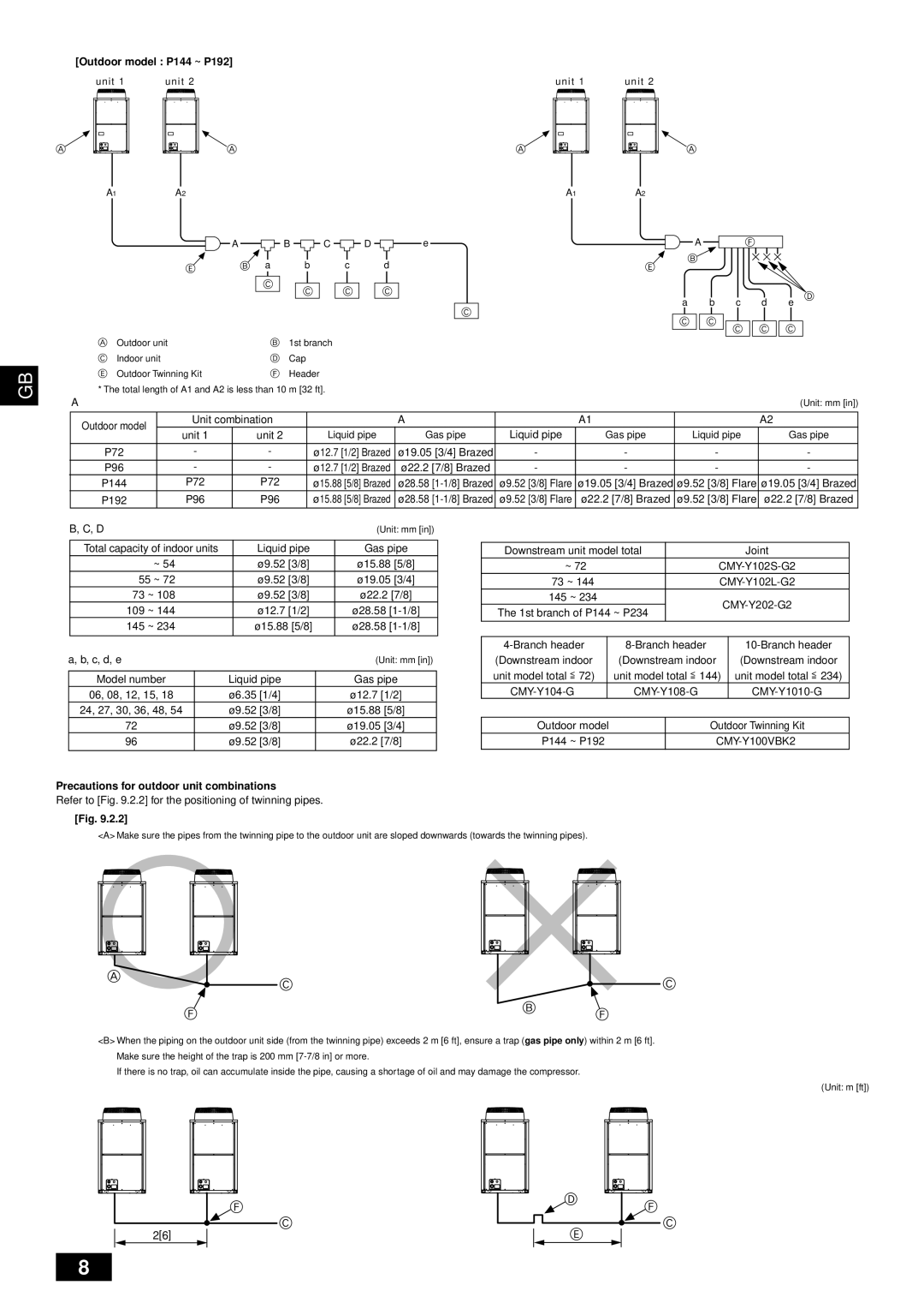
<Additional Charge>
<Example> |
|
|
|
| |
Indoor |
|
|
|
| |
1: 48 A: ø12.7 mm [1/2"] | 40 m [131 ft] | a: ø9.52 mm [3/8"] | 10 m [32 ft] |
| |
2: 36 | B: ø9.52 mm [3/8"] | 10 m [32 ft] | b: ø9.52 mm [3/8"] | 5 m [16 ft] | At the |
3: 15 | C: ø9.52 mm [3/8"] | 15 m [49 ft] | c: ø6.35 mm [1/4"] | 10 m [32 ft] | conditions |
4: 12 | D: ø9.52 mm [3/8"] | 10 m [32 ft] | d: ø6.35 mm [1/4"] | 10 m [32 ft] | below: |
5: 24 |
|
| e: ø9.52 mm [3/8"] | 10 m [32 ft] |
|
The total length of each liquid line is as follows: ø12.7 mm [1/2"]: A = 40 m [131 ft] = 40 m [131 ft] ø9.52 mm [3/8"]: B + C + D + a + b + e
=10 m [32 ft] + 15 m [49 ft] + 10 m [32 ft] + 10 m [32 ft] + 5 m [16 ft] + 10 m [32 ft] = 60 m [193 ft]
ø6.35 mm [1/4"]: c + d = 10 m [32 ft] + 10 m [32 ft] = 20 m [64 ft] Therefore,
<Calculation example> Additional refrigerant charge
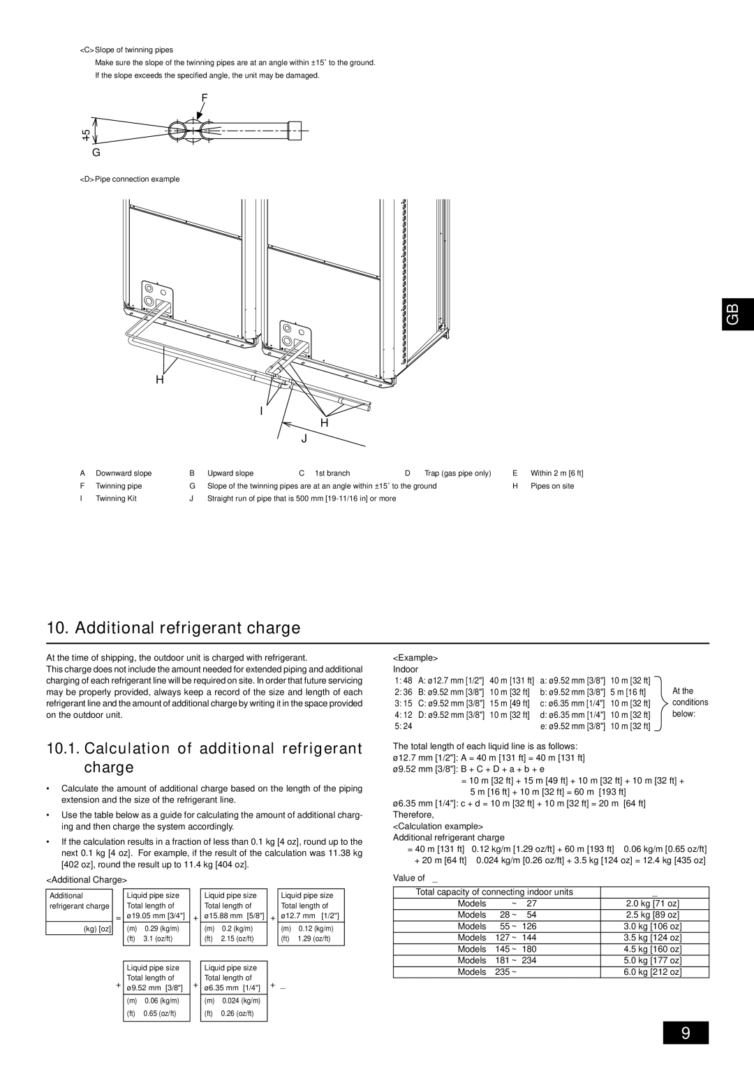
=40 m [131 ft] ⋅ 0.12 kg/m [1.29 oz/ft] + 60 m [193 ft] ⋅ 0.06 kg/m [0.65 oz/ft] + 20 m [64 ft] ⋅ 0.024 kg/m [0.26 oz/ft] + 3.5 kg [124 oz] = 12.4 kg [435 oz]
Value of α
Additional refrigerant charge
(kg) [oz]
=
+
Liquid pipe size Total length of ø19.05 mm [3/4"]
(m)⋅ 0.29 (kg/m) (ft) ⋅ 3.1 (oz/ft)
Liquid pipe size Total length of ø9.52 mm [3/8"]
(m)⋅ 0.06 (kg/m) (ft) ⋅ 0.65 (oz/ft)
+
+
Liquid pipe size Total length of ø15.88 mm [5/8"]
(m)⋅ 0.2 (kg/m) (ft) ⋅ 2.15 (oz/ft)
Liquid pipe size Total length of ø6.35 mm [1/4"]
(m)⋅ 0.024 (kg/m) (ft) ⋅ 0.26 (oz/ft)
Liquid pipe size Total length of
+ø12.7 mm [1/2"]
(m)⋅ 0.12 (kg/m) (ft) ⋅ 1.29 (oz/ft)
+α
Total capacity of connecting indoor units | α | |||
Models |
| ~ | 27 | 2.0 kg [71 oz] |
Models | 28 | ~ | 54 | 2.5 kg [89 oz] |
Models | 55 | ~ | 126 | 3.0 kg [106 oz] |
Models | 127 | ~ | 144 | 3.5 kg [124 oz] |
Models | 145 | ~ | 180 | 4.5 kg [160 oz] |
Models | 181 | ~ | 234 | 5.0 kg [177 oz] |
Models | 235 | ~ |
| 6.0 kg [212 oz] |
9
