MOUNTING THE CONTROL
UNIT
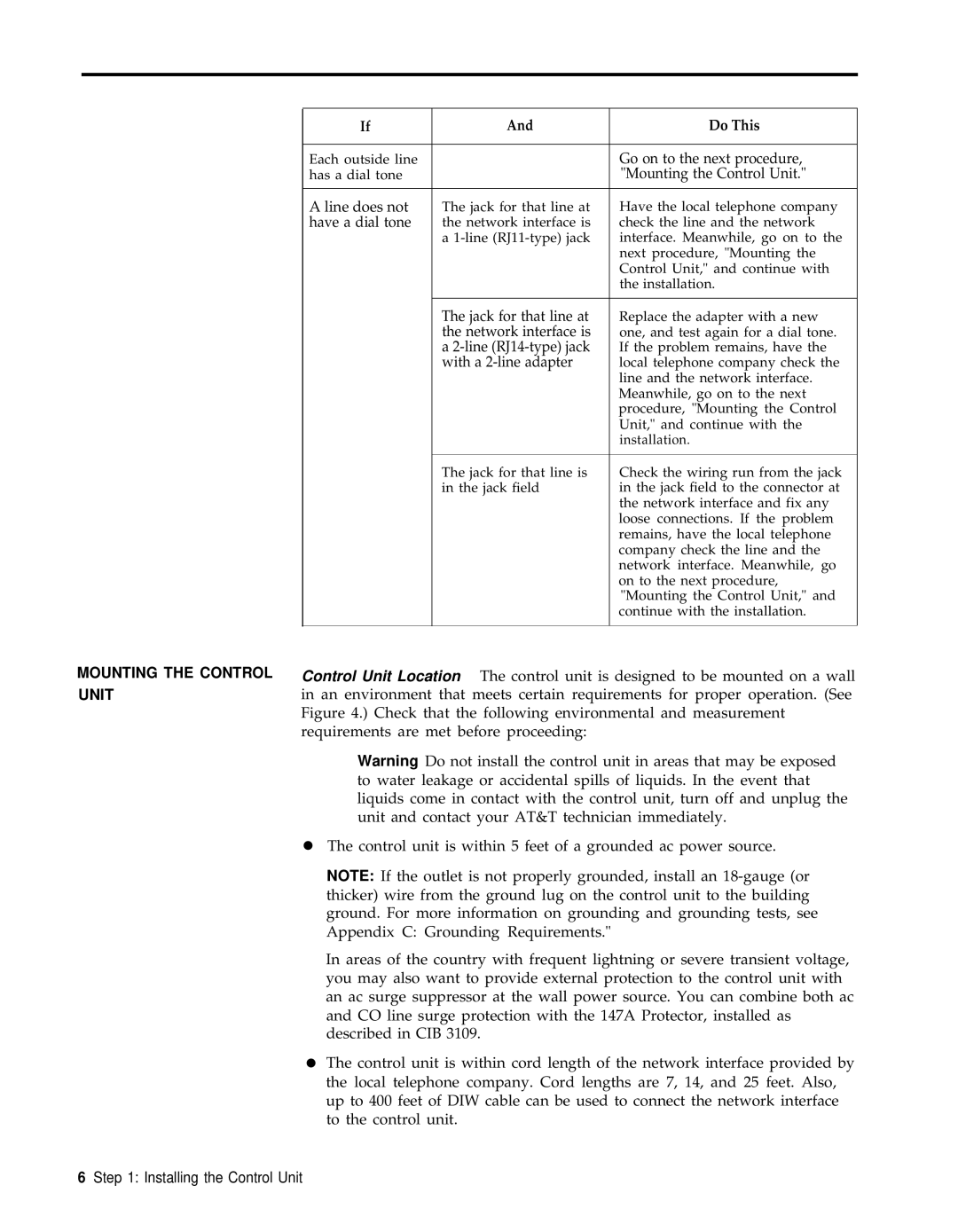
If | And | Do This |
|
|
|
Each outside line |
| Go on to the next procedure, |
has a dial tone |
| "Mounting the Control Unit." |
|
|
|
A line does not | The jack for that line at | Have the local telephone company |
have a dial tone | the network interface is | check the line and the network |
| a | interface. Meanwhile, go on to the |
|
| next procedure, "Mounting the |
|
| Control Unit," and continue with |
|
| the installation. |
|
|
|
| The jack for that line at | Replace the adapter with a new |
| the network interface is | one, and test again for a dial tone. |
| a | If the problem remains, have the |
| with a | local telephone company check the |
|
| line and the network interface. |
|
| Meanwhile, go on to the next |
|
| procedure, "Mounting the Control |
|
| Unit," and continue with the |
|
| installation. |
|
|
|
| The jack for that line is | Check the wiring run from the jack |
| in the jack field | in the jack field to the connector at |
|
| the network interface and fix any |
|
| loose connections. If the problem |
|
| remains, have the local telephone |
|
| company check the line and the |
|
| network interface. Meanwhile, go |
|
| on to the next procedure, |
|
| "Mounting the Control Unit," and |
|
| continue with the installation. |
|
|
|
Control Unit Location The control unit is designed to be mounted on a wall in an environment that meets certain requirements for proper operation. (See Figure 4.) Check that the following environmental and measurement requirements are met before proceeding:
Warning Do not install the control unit in areas that may be exposed to water leakage or accidental spills of liquids. In the event that liquids come in contact with the control unit, turn off and unplug the unit and contact your AT&T technician immediately.
●The control unit is within 5 feet of a grounded ac power source.
NOTE: If the outlet is not properly grounded, install an
In areas of the country with frequent lightning or severe transient voltage, you may also want to provide external protection to the control unit with an ac surge suppressor at the wall power source. You can combine both ac and CO line surge protection with the 147A Protector, installed as described in CIB 3109.
●The control unit is within cord length of the network interface provided by the local telephone company. Cord lengths are 7, 14, and 25 feet. Also, up to 400 feet of DIW cable can be used to connect the network interface to the control unit.