12
Docking station functionality
Docking station components
The table below explains the EdgeDock1 or EdgeDock5 LED indicators, power connector, USB connector, and contact pins.
Docking station | Explanation |
components |
|
Charging indicator | Identifies if the dosimeter is “charging” or “fully charged”. A red blinking LED |
| indicates the dosimeter is charging. A solid green LED equates to a fully |
| charged dosimeter. (Note the charging indicator is the first, or top, LED |
| indicator.) |
Power indicator | A red LED indicates the docking station is powered on. |
|
|
Power connector | Attach the power connector cable to the docking station in order to charge |
| the dosimeter(s). |
USB connector | Attach the USB connector to communicate with the dosimeter(s). |
Charge Contacts | Placing the dosimeter (s) onto the charge contacts allows charging and |
| communication. |
Table 2-2: EdgeDock1 and EdgeDock5 components
The EdgeDock1 and EdgeDock5 are powered by a
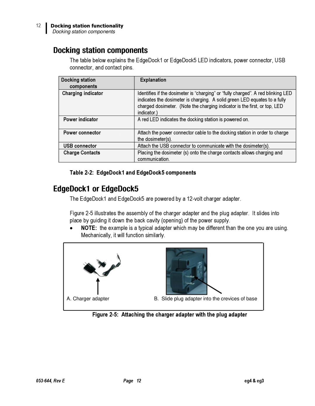
Figure 2-5 illustrates the assembly of the charger adapter and the plug adapter. It slides into place by guiding it down the back cavity (opening) of the power supply.
∙NOTE: the example is a typical adapter which may be different than the one you are using. Mechanically, it will function similarly.
A. Charger adapter | B. Slide plug adapter into the crevices of base |
Figure 2-5: Attaching the charger adapter with the plug adapter
Page 12 | eg4 & eg3 |