System Board Layout
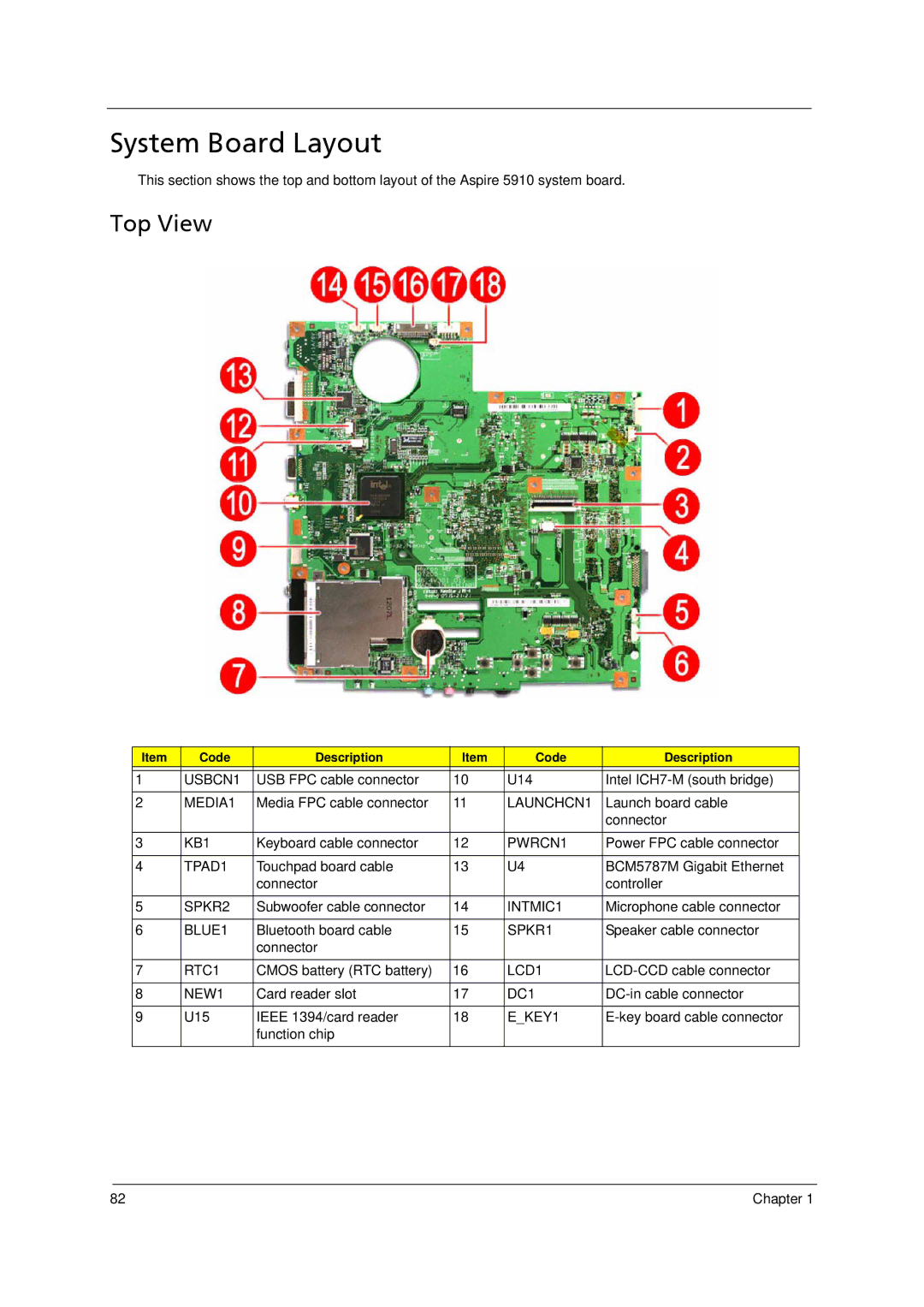
This section shows the top and bottom layout of the Aspire 5910 system board.
Top View
Item | Code | Description | Item | Code | Description |
|
|
|
|
|
|
1 | USBCN1 | USB FPC cable connector | 10 | U14 | Intel |
|
|
|
|
|
|
2 | MEDIA1 | Media FPC cable connector | 11 | LAUNCHCN1 | Launch board cable |
|
|
|
|
| connector |
|
|
|
|
|
|
3 | KB1 | Keyboard cable connector | 12 | PWRCN1 | Power FPC cable connector |
|
|
|
|
|
|
4 | TPAD1 | Touchpad board cable | 13 | U4 | BCM5787M Gigabit Ethernet |
|
| connector |
|
| controller |
|
|
|
|
|
|
5 | SPKR2 | Subwoofer cable connector | 14 | INTMIC1 | Microphone cable connector |
|
|
|
|
|
|
6 | BLUE1 | Bluetooth board cable | 15 | SPKR1 | Speaker cable connector |
|
| connector |
|
|
|
|
|
|
|
|
|
7 | RTC1 | CMOS battery (RTC battery) | 16 | LCD1 | |
|
|
|
|
|
|
8 | NEW1 | Card reader slot | 17 | DC1 | |
|
|
|
|
|
|
9 | U15 | IEEE 1394/card reader | 18 | E_KEY1 | |
|
| function chip |
|
|
|
|
|
|
|
|
|
82 | Chapter 1 |