Serviceguide
Revision History
General information
/TPH15spoolM program
Page
Chapter
System Utilities
Machine Maintenance Procedures
Troubleshooting
FRU Field Replaceable Unit List
Page
Chapter
Features
Page
Page
Features
Audio Subsystem
Graphics
Privacy Control
AMD Radeon HD 6850M
Optical Media Drive
Communication
Webcam
BD-R DL
Dimension and Weight
Power Adapter and Battery
Ports
Warranty
Special Keys and Controls
Environment
Optional Items
Software
Web links and utilities
Top View
Top View Icon Description
Controller Communication
Hardware Specifications and Configurations
Media Console
Media Console Icon Description Movie
Closed Front View
Closed Front View Icon Description
Rear View
Left View
Left View Icon Description
Left View Icon Description
Right View
Right View Icon Description
Base View
Base View Icon Description
Touchpad Basics
Touchpad Function Main TouchPad Left Button Right Button
Using the Keyboard
Desired access Num Lock on Num Lock off
Lock Keys
Embedded Numeric Keypad
Windows Keys
10. Windows Keys
Functions supported by Windows XP
Hot Keys
11. Keyboard Hot Keys
Keyboard Hot Keys
System Block Diagram
11. System Block Diagram
Specification Tables
Computer specifications Metric Imperial
System Board Major Chips Specification
Processor Specification
CPU
FSB DMI/QBI
Page
Video Interface Specification
Bios
Slot 1 MB Slot 2 MB Slot 3MB Slot 4MB Total Memory
W25X16AVSSIG W25Q32BVSSIG
LAN Interface Specification
Keyboard Specification
LSO/TCO
Hard Disk Drive AVL components Specification
WD5000BPVT
WD6400BPVT WD7500BPVT
MK7559GSXP
Super-Multi Drive Specification
Hlds
GT32N GT34N
DVD
UJ8A0
DVD-VIDEO, DVD-ROM DVD-R4.7GB, DVD-R DL
DVD+R, DVD+R DL, DVD+RW DVD-RAM4.7GB
BDC-TD03RS DVR-TD10RS
CD-ROM
DVD-RAM
BD9
Specification
Plds
DS-8A5SH
CD-ROM DVD-ROM
DVD-RW, DVD+RW, DVD-R 4.7G
BD Drive Items Specifications
UJ141AL
Items Specifications
DS-4E1S
DVD+RW 4.7G, DVD+R, DVD+R DL, DVD-R DL, DVD-RAM
BD-ROM, BD-ROM DL, BD-R, BD-R DL, BD-RE, BD-RE DL
LED Specification
LCD Inverter not available with this model Specification
CHI MEI
Graphics Controller Specification
ATI
Bluetooth Interface Specifications
Bluetooth Module Specifications
Camera Specification
JST SM08B Surs TF JST SM06B-XSRK-ETB
Mini Card Specification
3G Card not available in this model Specification
Audio Codec and Amplifier Specification
Audio Interface Specification
Wireless Module 802.11b/g/n Specification
PCI-E
Battery Specification
USB Port Specification
Hdmi Port Specification
Vram
AC Adapter Specification
System Power Management Specification
Card Reader Specification
QFN
Specification
System LED Indicator Specification
System DMA Specification Legacy Mode Power Management
System Interrupt Specification Hardware IRQ System Function
Hardware Specifications and Configurations
CF8-CFF
E000-EFFF
System Utilities
Bios Setup Utility
Bios Setup Utility
Navigating the Bios Utility
Bios Information Parameter Description
Information
Uuid
Bios Main Parameter Description Format/Option
Main
D2D
Bios Security Parameter Description Option
Security
Setting a Password
Removing a Password
Changing a Password
Setup Notice
Setup Warning Invalid Password
Boot
10. Bios Boot
Exit
Exit Parameters Description
Bios Flash Utilities
12. Bios Boot
DOS Flash Utility
13. DOS Flash Process
WinFlash Utility
15. InsydeFlash
Remove HDD/BIOS Password Utilities
Example UnlockHD
18. Unlock Password
Removing Bios Passwords
Method
Using DMITools
Miscellaneous Tools
22. Asset Tag Menu Item
24. Serial Number Menu Item
26. Exit Menu Item
Using the LAN MAC Eeprom Utility
System Utilities
Machine Maintenance Procedures
Page
Page
Page
Introduction
Tools
Screw Table
Screws
Maintenance Flowchart
Wlan Dimm
PCH
CPU
Getting Started
AC Adapter Outlet
Battery Pack Removal
Battery Pack Installation
Dummy Card Installation
Dummy Card Removal
Base Door Installation
Base Door Removal
HDD Hard Disk Drive Module Removal
Lower Cover Overview with Base Door Removed
HDD Module Installation
Dimm Module Installation
Dimm Dual In-line Memory Module Module Removal
Wlan Wireless Local Area Network Module Removal
Wlan Module Installation
Slave HDD Door Installation
Slave HDD Door Removal
Slave HDD Module Installation
Slave HDD Module Removal
ODD Optical Disk Drive Module Removal
12. ODD Module in Lower Cover
ODD Module Installation
Keyboard Removal
14. Lower Cover Screws
15. Keyboard Frame
Keyboard Installation
17. Keyboard Module
Machine Maintenance Procedures
LCD Liquid Crystal Display Module Removal
19. Wlan Module Cables
21. LCD Module Cables
LCD Module Installation
Upper Cover Removal
23. Upper Cover Cables
Upper Cover Installation
Microphone Module Removal
25. Overview of Upper Cover Modules and Cables
Microphone Module Installation
Bluetooth Module Removal
Bluetooth Module Installation
Touchpad Board Removal
28. Touchpad Board and Module Cables
Touchpad Board Installation
Finger Print Module Installation
Fingerprint Module Removal
LAN Module Removal
31. Lower Cover with Modules
LAN Module Installation
USB Module Installation
USB Module Removal
CCA B
34. Mainboard Connectors Top
Mainboard Removal
35. Mainboard Connectors Bottom
Mainboard Installation
Speaker and Subwoofer Assembly Removal
Speaker and Subwoofer Assembly Installation
RTC Battery Removal
38. Mainboard bottom Overview
RTC Battery Installation
Thermal Module Removal
40. Thermal Module
Thermal Module Installation
41. Applying Grease to CPU
Page
CPU Installation
CPU Removal
PCH Heatsink Removal
43. PCH Heatsink
PCH Heatsink Installation
44. Mainboard Recycling
LCD Module Removal and Installation Instructions
Troubleshooting
Intermittent Problems Undetermined Problems Post Codes
Common Problems
Power On Issues
Computer Shuts Down Intermittently
No Display Issues
No Post or Video
Abnormal Video
LCD Failure
LCD Failure
Keyboard Failure
Keyboard Failure
Touchpad Failure
Touchpad Failure
Sound Problems
Internal Speaker Failure
Troubleshooting
Microphone Failure
Microphone Failure
USB Failure
USB Failure
Other Functions Failure
Intermittent Problems
Undetermined Problems
Post Code Range Phase
Post Codes
Peicpuhtreset PEI
Isis Peimemoryinstall PEI
Peiswitchstack PEI
Peienterrecoverymo PEI
Peirecoverymediafo PEI
UND Peirecoverymediano PEI
Tfound Peirecoveryloadfile PEI
Done Peirecoverystartfla PEI
BDS Phase Post Code Table
Phase Post Code Description
BDS Phase Post Code Table Functionality Name Description
Allbootoption
Tselection Bdsentersetup BDS
Bdsenterboot BDS
Manager Bdsbootdevice BDS
Acpi Functions Post Code Table
SMM Functions Post Code Table
Page
Jumper and Connector Locations
Page
Mainboard Jumper and Connector Locations
USB 3.0 Conn PJ1 Battery Conn
Wifi Conn
VGA Conn
FAN Conn
Clearing Password Check and Bios Recovery
Clearing Password Check
Steps for Clearing Bios Password Check
Bios Recovery by Crisis Disk
Bios Recovery Boot Block
Bios Recovery Hot key
Clear Cmos Jumper
Steps for Bios Recovery from USB Storage
Jumper and Connector Locations
FRU Field Replaceable Unit List
Exploded Diagrams FRU List Screw List
FRU Field Replaceable Unit List
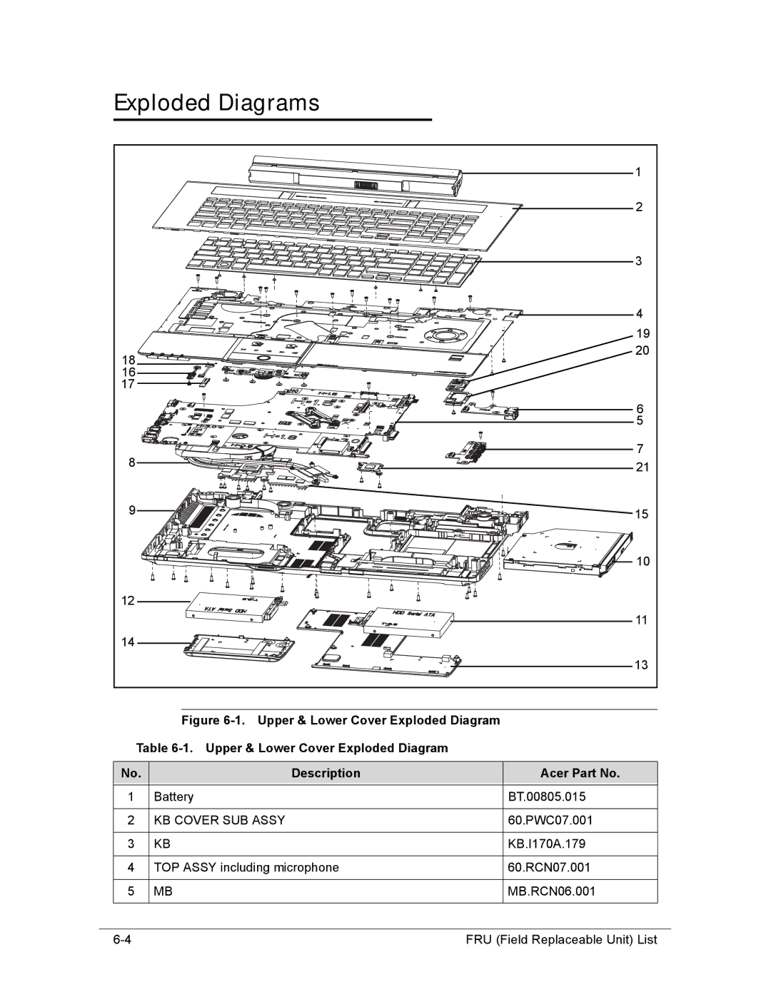
Exploded Diagrams
KB Cover SUB Assy
Bluetooth Module
Bluetooth Cable
LAN/B Assy
USB/B Assy
LCD Assembly Exploded Diagram
86.A08V7.004
Battery
FRU List
FRU List Category Description
Adapter
Cable
CASE/COVER/BRACKET Assembly
2ND HDD Door for Empty
FP Bracker
Dummy Card
CPU/PROCESSOR
Sata ODD Bezel SUPER-MULTI
ODD Bracket
BD Combo Drive
ODD Bezel Blue RAY
BD RW Drive
HDD/HARD Disk Drive
8MB LF F/WGJ001J
Sata 8MB LF F/W0001SDM1
HDD
3265GSXSATA8MBLFF/WGJ001J
Sata 8MB LF+HF F/WGNDD3J HDD Connector Cable
LF F/WGJ001J
WD6400BPVT-22HXZT1, ML375M Sata 8MB
LF F/WGJ002J
FRU List Category Description
LCD Module
Mainboard
Memory
Heatsink
Speaker
Miscellaneous
Screw List
Screw List
Screw
FRU Field Replaceable Unit List
Model Definition and Configuration
AS8950G
AS8950G
RO, Description
W7HP64ASES1 MC
V3J
W7HP64ASWW1 MC
W7HP64ASDK2 MC
W7HP64EMASTR1 MC
W7HP64RUASRU1 MC
W7HP64EMASPH1 MC
W7UT64EMASPH1 MC
W7HP64ASGR1 MC
W7HP64ASIT1 MC
AAP AU/NZ
W7HP64EMASZA2 MC
LX.RCN02.009 AS8950G-2638G1.5TWnss
W7UT64ASWW1 MC
CPU, LCD
NLED18.4WUXGAGL
AS8950G-263161.5T LX.RCN02.023 Ci72630QM
AS8950G-2638G1.5T LX.RCN02.003 Ci72630QM
VGA Chip, Vram
Granvilepro 2G-DDR3
Whistlerpro
AS8950G-2634G LX.RCR02.002
Memory 1
SO4GBIII10
SO2GBIII10
SO4GBIII10 SO2GBIII10
AS8950G-2638G1 LX.RCN02.005
Memory 3
5TBnss AS8950G-2638G1 LX.RCN02.020 LX.RCN02.005 LX.RCN02.021
HDD 1
HDD 1
LX.RCR02.010 N750GB5.4KS 5TBnss AS8950G-2728G1
ODD, Wireless LAN
NBDCB4XS
NBDRW4XS
NSM8XS
AS8950G-2636G1 LX.RCN02.013
Bluetooth, NB Chipset
LX.RCR02.010 HM65 AS8950G-2728G1.5TMnss
Model Definition and Configuration
Test Compatible Components
Microsoft Windows 7 Environment Test
Test Compatible Components
Microsoft Windows 7 Environment Test
Test Compatible Components
2nd HDD
Adapter
Bluetooth
Audio Codec
Camera
Chicony
Card Reader
ODM SC, XD
Intel
Finger Print
Egis
HDD
LF+HF F/WGNDD3J
ML320M,WD Sata 8MB LF
60002005 N320GB5.4KS HDD Hgst 2.5 5400rpm 320GB KH.32007.008
Keyboard
LAN
LCD
MEM
NB Chipset
ODD
Sony
Philips
NBDCB4XS ODD Panasonic BD Combo
SB Chipset
TV Antenna
TV Tuner
USB Controller
VGA Chip
WiFi Antenna
Wireless LAN
Pifa
WNC
Online Support Information
Introduction
Online Support Information
Online Support Information