POST Check Points
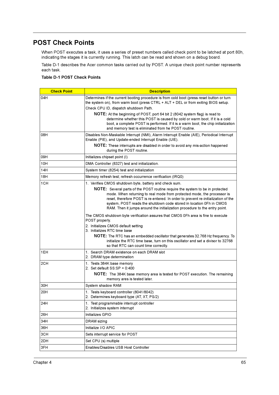
When POST executes a task, it uses a series of preset numbers called check point to be latched at port 80h, indicating the stages it is currently running. This latch can be read and shown on a debug board.
Table
Table D-1 POST Check Points
Check Point |
| Description |
|
| |
04H | Determines if the current booting procedure is from cold boot (press reset button or turn | |
| the system on), from warm boot (press CTRL + ALT + DEL or from exiting BIOS setup. | |
| Check CPU ID, dispatch shutdown Path. | |
|
| NOTE: At the beginning of POST, port 64 bit 2 (8042 system flag) is read to |
|
| determine whether this POST is caused by cold or warm boot. If it is a cold |
|
| boot, a complete POST is performed. If it is a warm boot, the chip initialization |
|
| and memory test is eliminated from he POST routine. |
|
| |
08H | Disables | |
| Enable (PIE), and | |
|
| NOTE: These interrupts are disabled in order to avoid any |
|
| during the POST routine. |
|
| |
09H | Initializes chipset point (I) | |
|
| |
10H | DMA Controller (8327) test and initialization. | |
|
| |
14H | System timer (8254) test and initialization | |
|
| |
18H | Memory refresh test; refresh occurrence verification (IRQ0) | |
|
|
|
1CH | 1. | Verifies CMOS shutdown byte, battery and check sum. |
|
| NOTE: Several parts of the POST routine require the system to be in protected |
|
| mode. When returning to real mode from protected mode, the processor is |
|
| reset, therefore POST is |
|
| system, POST reads the shutdown code stored in location 0Fh in CMOS |
|
| RAM. Then it jumps around the initialization procedure to the entry point. |
| The CMOS shutdown byte verification assures that CMOS 0Fh area is fine to execute | |
| POST properly. | |
| 2. | Initializes CMOS default setting |
| 3. | Initializes RTC time base |
|
| NOTE: The RTC has an embedded oscillator that generates 32.768 Hz frequency. To |
|
| initialize the RTC time base, turn on this oscillator and set a divisor to 32768 |
|
| so that RTC can count time correctly. |
|
|
|
1EH | 1. | Search DRAM existence on each DRAM slot |
| 2. | DRAM type determination |
|
|
|
2CH | 1. | Tests 384K base memory |
| 2. | Set default SS:SP = 0:400 |
|
| NOTE: The 384K base memory area is tested for POST execution. The remaining |
|
| memory ares is tested later. |
|
| |
30H | System shadow RAM | |
|
|
|
20H | 1. | Tests keyboard controller (8041/8042) |
| 2. | Determines keyboard type (AT, XT, PS/2) |
|
|
|
24H | 1. | Test programmable interrupt controller |
| 2. | Initializes system interrupt |
|
| |
26H | Initializes GPIO | |
|
| |
34H | DRAM sizing | |
|
| |
36H | Initialize I/O APIC | |
|
| |
3CH | Sets interrupt service for POST | |
|
| |
2DH | Set CPU (s) multiple | |
|
| |
3FH | Enables/Disables USB Host Controller | |
|
|
|
Chapter 4 | 65 |