14 | 2 System tour |
System board
Mainboard layout
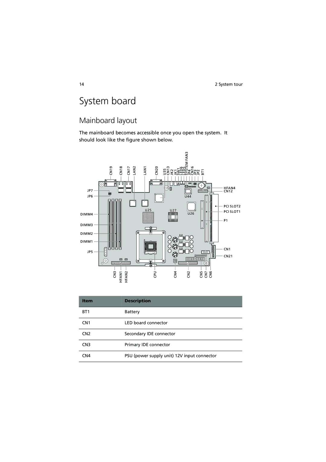
The mainboard becomes accessible once you open the system. It should look like the figure shown below.
Item | Description |
|
|
BT1 | Battery |
|
|
CN1 | LED board connector |
|
|
CN2 | Secondary IDE connector |
|
|
CN3 | Primary IDE connector |
|
|
CN4 | PSU (power supply unit) 12V input connector |
|
|