The Main Application Window
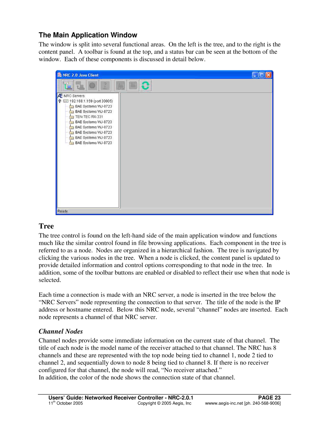
The window is split into several functional areas. On the left is the tree, and to the right is the content panel. A toolbar is found at the top, and a status bar can be seen at the bottom of the window. Each of these components is discussed in detail below.
Tree
The tree control is found on the
Each time a connection is made with an NRC server, a node is inserted in the tree below the
“NRC Servers” node representing the connection to that server. The title of the node is the IP address or hostname entered. Below this NRC node, several “ channel” nodes are inserted. Each node represents a channel of that NRC server.
Channel Nodes
Channel nodes provide some immediate information on the current state of that channel. The title of each node is the model name of the receiver attached to that channel. The NRC has 8 channels and these are represented with the top node being tied to channel 1, node 2 tied to channel 2, and sequentially down to node 8 being tied to channel 8. If there is no receiver configured for that channel, the node will read, “ No receiver attached.”
In addition, the color of the node shows the connection state of that channel.
Users’ Guide: Networked Receiver Controller - | PAGE 23 |
11th October 2005 | Copyright © 2005 Aegis, Inc |