Table |
|
| |
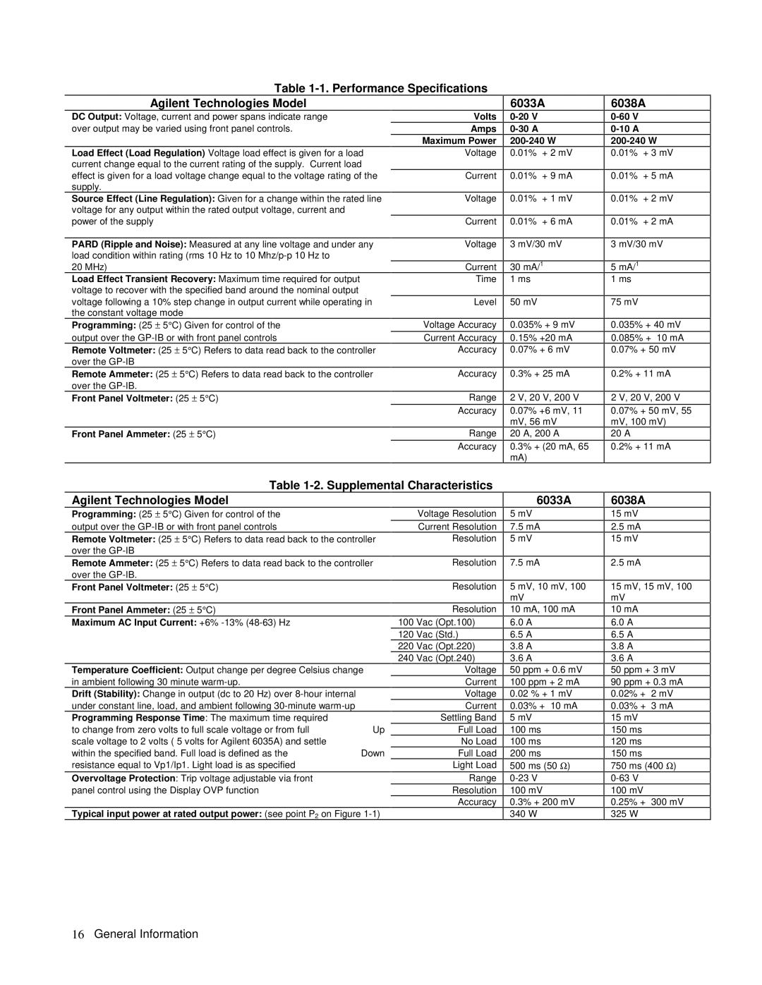
Agilent Technologies Model |
| 6033A | |
DC Output: Voltage, current and power spans indicate range | Volts |
| |
over output may be varied using front panel controls. | Amps |
| |
| Maximum Power | ||
Load Effect (Load Regulation) Voltage load effect is given for a load | Voltage | 0.01% | + 2 mV |
current change equal to the current rating of the supply. Current load |
|
|
|
effect is given for a load voltage change equal to the voltage rating of the | Current | 0.01% | + 9 mA |
supply. |
|
|
|
6038A
0-10 A
200-240 W
0.01% + 3 mV
0.01% + 5 mA
Source Effect (Line Regulation): Given for a change within the rated line voltage for any output within the rated output voltage, current and power of the supply
PARD (Ripple and Noise): Measured at any line voltage and under any load condition within rating (rms 10 Hz to 10
20 MHz)
Load Effect Transient Recovery: Maximum time required for output voltage to recover with the specified band around the nominal output voltage following a 10% step change in output current while operating in the constant voltage mode
Programming: (25 ± 5°C) Given for control of the output over the
Remote Voltmeter: (25 ± 5°C) Refers to data read back to the controller over the
Remote Ammeter: (25 ± 5°C) Refers to data read back to the controller over the
Front Panel Voltmeter: (25 ± 5°C)
Front Panel Ammeter: (25 ± 5°C)
Voltage | 0.01% | + 1 mV |
|
|
|
Current | 0.01% | + 6 mA |
|
| |
Voltage | 3 mV/30 mV | |
|
| |
Current | 30 mA/1 | |
Time | 1 ms |
|
|
|
|
Level | 50 mV |
|
|
| |
Voltage Accuracy | 0.035% + 9 mV | |
Current Accuracy | 0.15% | +20 mA |
Accuracy | 0.07% | + 6 mV |
|
| |
Accuracy | 0.3% + 25 mA | |
|
| |
Range | 2 V, 20 V, 200 V | |
Accuracy | 0.07% +6 mV, 11 | |
| mV, 56 mV | |
Range | 20 A, 200 A | |
Accuracy | 0.3% + (20 mA, 65 | |
| mA) |
|
0.01% + 2 mV
0.01% + 2 mA
3 mV/30 mV
5mA/1
1ms
75 mV
0.035% + 40 mV
0.085% + 10 mA
0.07% + 50 mV
0.2% + 11 mA
2 V, 20 V, 200 V
0.07% + 50 mV, 55 mV, 100 mV)
20 A
0.2% + 11 mA
Table |
| ||
Agilent Technologies Model |
|
| 6033A |
Programming: (25 ± 5°C) Given for control of the |
| Voltage Resolution | 5 mV |
output over the |
| Current Resolution | 7.5 mA |
Remote Voltmeter: (25 ± 5°C) Refers to data read back to the controller | Resolution | 5 mV | |
over the |
|
|
|
Remote Ammeter: (25 ± 5°C) Refers to data read back to the controller | Resolution | 7.5 mA | |
over the |
|
|
|
Front Panel Voltmeter: (25 ± 5°C) |
| Resolution | 5 mV, 10 mV, 100 |
|
|
| mV |
Front Panel Ammeter: (25 ± 5°C) |
| Resolution | 10 mA, 100 mA |
Maximum AC Input Current: +6% |
| 100 Vac (Opt.100) | 6.0 A |
|
| 120 Vac (Std.) | 6.5 A |
|
| 220 Vac (Opt.220) | 3.8 A |
|
| 240 Vac (Opt.240) | 3.6 A |
Temperature Coefficient: Output change per degree Celsius change | Voltage | 50 ppm + 0.6 mV | |
in ambient following 30 minute |
| Current | 100 ppm + 2 mA |
Drift (Stability): Change in output (dc to 20 Hz) over |
| Voltage | 0.02 % + 1 mV |
under constant line, load, and ambient following |
| Current | 0.03% + 10 mA |
Programming Response Time: The maximum time required |
| Settling Band | 5 mV |
to change from zero volts to full scale voltage or from full | Up | Full Load | 100 ms |
scale voltage to 2 volts ( 5 volts for Agilent 6035A) and settle |
| No Load | 100 ms |
within the specified band. Full load is defined as the | Down | Full Load | 200 ms |
resistance equal to Vp1/Ip1. Light load is as specified |
| Light Load | 500 ms (50 Ω) |
Overvoltage Protection: Trip voltage adjustable via front |
| Range | |
panel control using the Display OVP function |
| Resolution | 100 mV |
|
| Accuracy | 0.3% + 200 mV |
Typical input power at rated output power: (see point P2 on Figure |
| 340 W | |
6038A
15mV
2.5mA
15mV
2.5 mA
15 mV, 15 mV, 100 mV
10mA
6.0A
6.5A
3.8A
3.6A
50ppm + 3 mV
90ppm + 0.3 mA 0.02% + 2 mV 0.03% + 3 mA
15mV
150ms
120ms
150ms
750ms (400 Ω)
100mV
0.25% + 300 mV
325W