Operating Manual
Certification
Environmental Conditions
Before Applying Power
Do not Service or Adjust Alone
General
Safety Symbols
EMC
Declaration
Manufacturer’s Declaration
Herstellerbescheinigung
Table Of Contents
Table Of Contents
Standard Commands for Programmable Instruments
VAC Input Power Option
Blank Front Panel Option
Index
Description
Introduction
Accessories
Safety Considerations
Options
Instrument and Manual Identification
Model
GP-IB Interconnection Cables and Connectors
GP-IB Compatibility
Ordering Additional Manuals
Related Documents
Specifications
Ieee
6038A
Performance Specifications Agilent Technologies Model 6033A
6035A
6030A
6031A
6032A
Supplemental Characteristics
6035A 6038A
Agilent Model
General Information
Preparation For Use
Initial Inspection
Power Connection
Input Power Requirements
Rack Mounting
Power-Cord Plug Configurations
Line Voltage Option Conversion
Installation
Line Voltage Conversion Components
Agilent Models 6030A, 6031A, 6032A, 6035A
AC Line Impedance Check
Repackaging For Shipment
Rear Panel Screw Sizes and Part Numbers
Agilent Model 6038A
Agilent Model 6033A
Operating Instructions
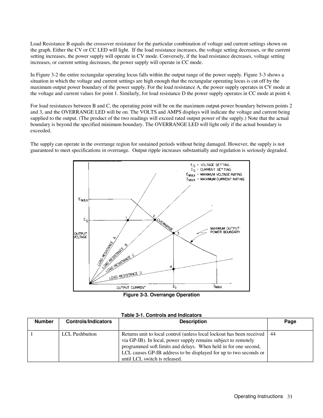
Output Range For An Autoranging Power Supply
Controls and Indicators
Overrange Operation Controls and Indicators Description
Number Controls/Indicators
Operating Instructions
OVP Adjust
Turn-On Checkout Procedure
Factory Settings, Mode Switch
Connecting the Load
Initial Setup and Interconnections
AWG
Maximum Wire Lengths To Limit Voltage Drops
Cross Section Area Mm2 Kft 10A 17 a
Cross Section Area in mm2 Ampacity
Stranded Copper Wire Ampacity Wire Size
Connecting a Bypass Capacitor Overvoltage Protection OVP
Foldback Protection
Remote Voltage Sensing
Remote Voltage Sensing
Mode Switches
Voltage Resistance
Mode Switches
Mode Switches Programming Mode
GP-IB/RPG
Protective Circuits
Monitor Signals
Constant Voltage Operation
Local Operation
Interface Functions
GP-IB Operation
Constant Current Operation
Return to Local
Operating Instructions
ERR RDY PON FAU
GP-IB Address Selection
RQS
Serial Poll Register
INH-FLT or RLY LNK Operation
Power-On Service Request
Initial Conditions
Programming Syntax
Output Adjust
OVP
VMAX? Vmax ?
Unmask CC,OR,FOLD Unmask CC, OR, Fold
Unmask CC or Fold
Vset 5 V VSET5V
VMAX? IMAX?
VSET? ISET? VOUT? IOUT? OVP?
GP-IB Commands Range or **Response To Query Description
Command
HOLD?
STS? ASTS?
TRG
SRQ OFF
FAULT?
UNMASK?
SRQ OFF SRQ SRQ on SRQ SRQ? CLR ERR?
Vout 15VIOUT 5A Vout 15V Iout 5A
TEST? ID?
FOLD? HOLD? OUT? SRQ?
Format of Numbers Sent from Power Supply
STS? FAULT? ASTS? ERR? UNMASK? TEST?
VSET? ISET? DLY? VOUT? IOUT? VMAX? IMAX?
Iset Iset 5 a Iset 5 MA
VSET?
OUT on RST
Vmax Imax Vmax 15 Imax 5 a Vmax 15 MV Imax 5 MA
DLY?
OUT ?
HOLD?
STO
Output PS1 Hold ON’’ 5A’’
STS?
ERR
Status Register Bit Position Bit Weight
Condition
Fold
Unmask CC, OR, ERR
Fault
Unmask
TEST?
No Errors
Error # 10. Status Register Errors Description
Analog Programming
Resistance Programming of Output Voltage
10. Voltage Programming of Output Voltage
Multiple-Supply Operation
12. Resistance Programming of Output Current
Series Operation
14. Auto-Parallel Operation
15. Series Operation
Fault Input FLT and Remote Inhibit INH Connections
16. FLT/INH Connections
19a. FLT and INH with Multiple Supplies
20. Timing Diagram
Page
Manual Changes
Using Appendix a
General Information Description
Scope of Appendix a
Section lll Manual Changes
Section ll Manual Changes
Page
Page
Introduction
Turn-On Check Out Procedure
Possible failure
STS
Table B-1. ID Query Response Agilent Model
Response
Vset 20 Iset
Overvoltage Protection Setting
Table B-2. CC Check Command String Agilent Model
String
Page
Standard Commands for Programmable Instruments Scpi
Introduction
Linked Connections
GP-IB
Parameters
Common Commands
Subsystem Commands
Keywords
Figure C-2. Common Command Syntax Diagram
PON CME EXE DDE QYE
Command Syntax
Bit Configuration of Standard Event Status Enable Register
Meaning and Type
ESR? *PSC *STB?
ESE?
ESR?
OPC?
Pending operations are complete when
Returned Parameters NR1
Command Syntax PSC bool Parameters
Default Value Example PSC
PSC?
RST
Command Syntax*SAV NRf Parameters Example
1MSS ESB MAV Ques
Bit Configuration of Status Byte Register
SRE?
Oper
Abor Abort
TRG
TST?
WAI
Curr Prot Stat 0 Current Protection State OFF
Command Syntax SOURceCURRentPROTectionSTATe bool Parameters
Currlev
Currprotstat
Outp 1 Output State ON, Norelay
Init Initiate Immediate
Initcont 1 Initiatecontinuous
Meas CURR? Meas VOLT? Measure Voltage DC? MV
OUTPPROTDEL? MIN OUTPPROTDEL? MAX
Outpprotdelmin Outputprotdelay MAX
Outpprot
Outp Prot CLE Output Protection Clear
Status Operation Registers
Bit Configuration of Operation Registers
STATOPEREVEN?
Status Questionable Registers
NTR/PTR Commands
Bit Configuration of Questionable Registers
Statpres
Statquesenab
STATQUESCOND?
STATQUESEVEN?
Systlang Tmsl Systemlanguage Compatibility
Syst ERR? System ERROR?
Statquesntr 16 Statusquestionableptr
STATQUESNTR? STATQUESPTR?
Trigsour
Volt PROT? Voltage Protection AMPLITUDE?
VOLTPROTAMPL?
Questionable Status Group
Standard Event Status Group
Bit Signal
Status Byte and Service Request Enable Registers
Questionable Status Group
Register
PTR NTR
Status Byte Register
Service Request Enable Register
Status Programming Examples
ESE
SRE
Standard Event Status Register Error Bits
Device-Dependent Errors
Output Queue
Error Number
Command Summary Subsystem Commands
Scpi Command Summary
Initimm Initcont INITCONT? MEASCURRDC?
Common Commands
Arps
ARPS/SCPI Commands
Table C-6. Comparison of Arps and Scpi Commands
Equivalent Scpi Command
Page
Output @PS Vset
Path Names
Initialization
Voltage and Current Programming
Output @PSVOUT? Enter @ PSA
Voltage and Current Readback
END While
ERR Fold
Output Inhibit / Enable
Power Supply Status
Present Status
Accumulated Status
Serial Poll
Fault and Mask Registers
Output @PSUNMASK CC, OR, OV,AC
SPOLLRESP= Spoll @PS
RQS ERR RDY PON FAU
Output @PSSRQ on Output @PS~SRQ OFF
Service Request
Programming Error Detection
Delay Time
Output @PS ERR? Enter @PSERRCODE
OFF KEY
Foldback
Fault Indicator FLT and Inhibit INH
Protection Functions
Overvoltage
Output @PSSTO 10RCL
Hold Mode
Advanced Topics
Machines States
210 ! Loop Through the States 10 Times
Page
Index
Atsl Ieee
GET
OC bit 98, 101
Tmsl
SH1 SR1
Asia Pacific
United States Canada
Europe Japan
Latin America Australia/New Zealand
Manual Updates