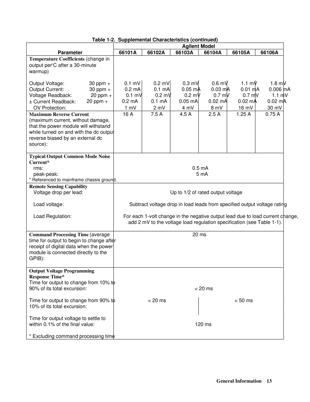
Table 1-2. Supplemental Characteristics (continued)
Parameter
Temperature Coefficients (change in output per °C after a
66101A
66102A
Agilent Model
66103A | 66104A |
66105A
66106A
Output Voltage: | 30 ppm + |
Output Current: | 30 ppm + |
Voltage Readback: | 20 ppm + |
± Current Readback: | 20 ppm + |
OV Protection: |
|
Maximum Reverse Current (maximum current, without damage, that the power module will withstand while turned on and with the dc output reverse biased by an external dc source):
Typical Output Common Mode Noise Current*
rms:
* Referenced to mainframe chassis ground.
0.1mV
0.2mA
0.1mV
0.2mA 1 mV 16 A
0.2 mV | 0.3 mV | 0.6 mV | 1.1 mV | 1.8 mV | |
0.1 mA | 0.05 mA | 0.03 mA | 0.01 mA | 0.006 mA | |
0.2 mV | 0.2 mV | 0.7 mV | 0.7 mV | 1.1 mV | |
0.1 mA | 0.05 mA | 0.02 mA | 0.02 mA | 0.02 mA | |
2 mV | 4 mV | 8 mV | 16 mV | 30 mV | |
7.5 A | 4.5 A | 2.5 A | 1.25 A | 0.75 A | |
|
|
|
|
|
0.5mA 5 mA
Remote Sensing Capability
Voltage drop per lead:
Load voltage:
Load Regulation:
Command Processing Time (average time for output to begin to change after receipt of digital data when the power module is connected directly to the GPIB):
Output Voltage Programming Response Time*
Time for output to change from 10% to
90% of its total excursion:
Time for output to change from 90% to
10% of its total excursion:
Time for output voltage to settle to within 0.1% of the final value:
Up to 1/2 of rated output voltage
Subtract voltage drop in load leads from specified output voltage rating
For each
add 2 mV to the voltage load regulation specification (see Table
20 ms
< 20 ms
< 20 ms | < 50 ms |
|
|
120 ms
* Excluding command processing time
