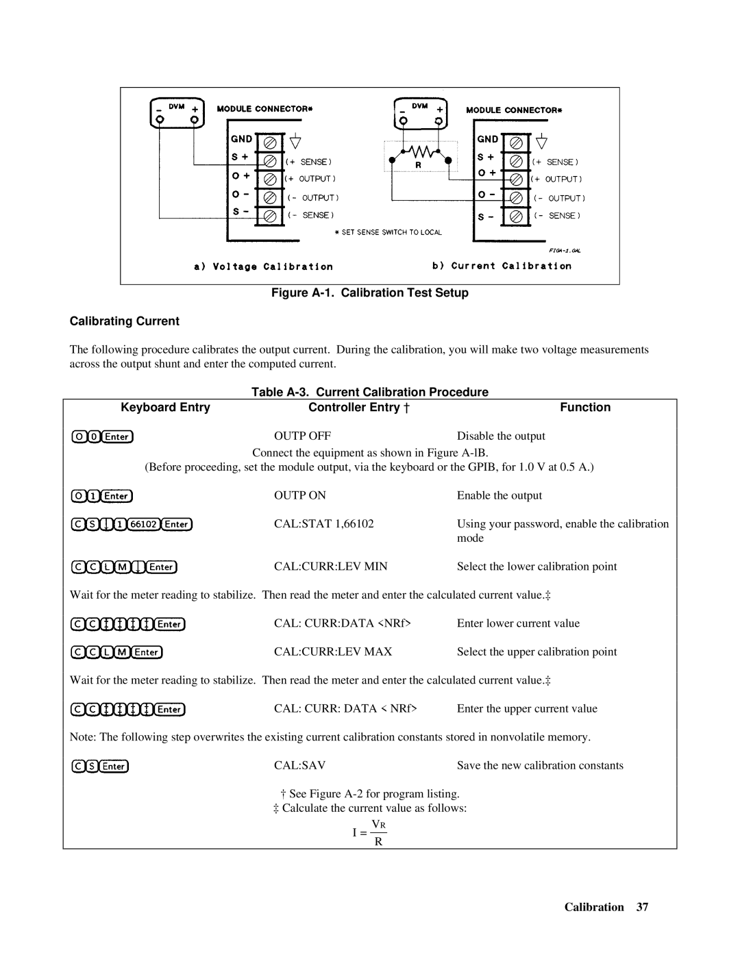
Figure A-1. Calibration Test Setup
Calibrating Current
The following procedure calibrates the output current. During the calibration, you will make two voltage measurements across the output shunt and enter the computed current.
| Table | ||
Keyboard Entry |
| Controller Entry † | Function |
|
| OUTP OFF | Disable the output |
|
| ||
|
|
|
|
Connect the equipment as shown in Figure
(Before proceeding, set the module output, via the keyboard or the GPIB, for 1.0 V at 0.5 A.)
OUTP ON | Enable the output |
CAL:STAT 1,66102 | Using your password, enable the calibration |
| mode |
CAL:CURR:LEV MIN | Select the lower calibration point |
Wait for the meter reading to stabilize. Then read the meter and enter the calculated current value.‡
CAL: CURR:DATA <NRf> | Enter lower current value |
CAL:CURR:LEV MAX | Select the upper calibration point |
Wait for the meter reading to stabilize. Then read the meter and enter the calculated current value.‡
CAL: CURR: DATA < NRf> | Enter the upper current value |
Note: The following step overwrites the existing current calibration constants stored in nonvolatile memory.
CAL:SAV | Save the new calibration constants |
†See Figure
‡Calculate the current value as follows:
VR
I =
R
Calibration 37
