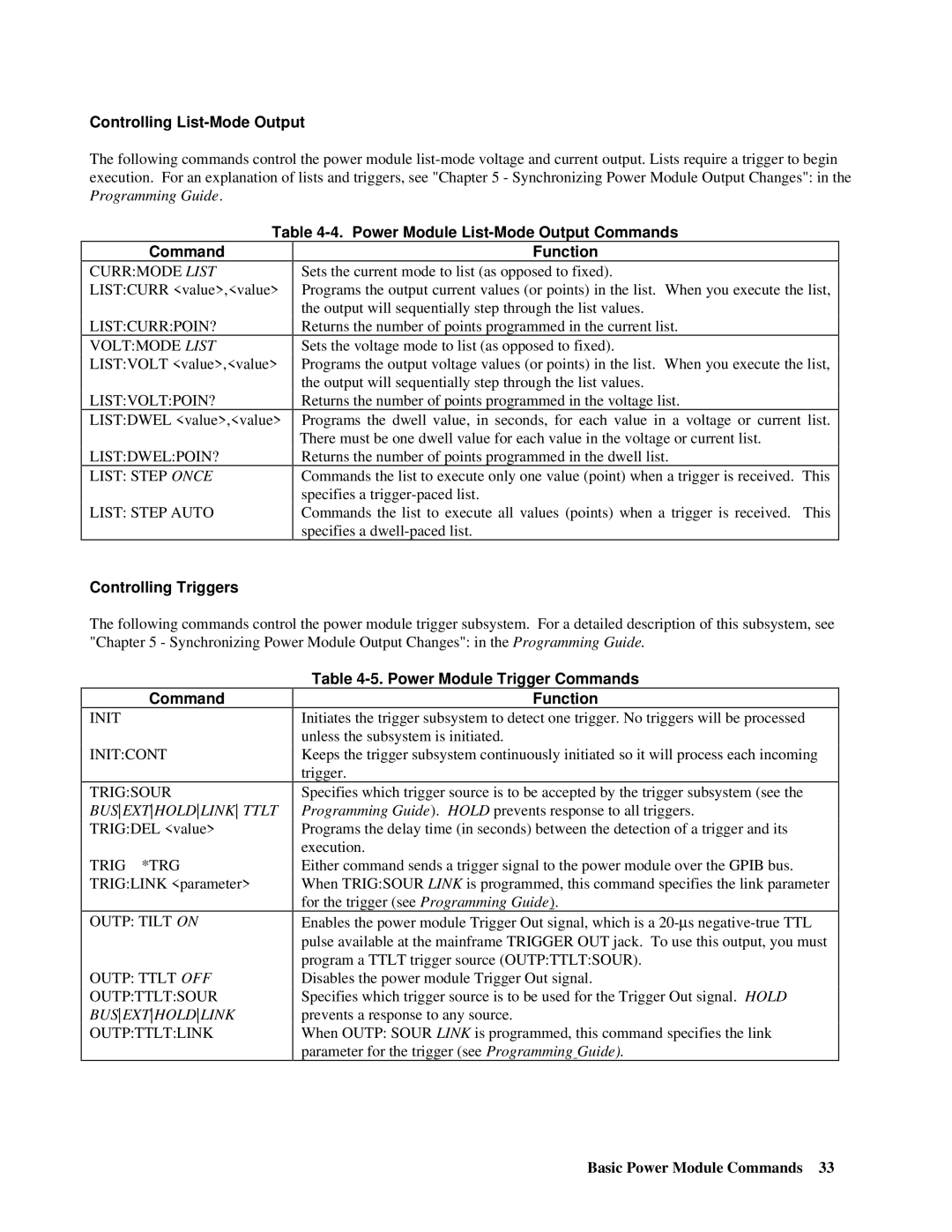
Controlling List-Mode Output
The following commands control the power module
| Table | |
Command |
| Function |
CURR:MODE LIST LIST:CURR <value>,<value>
LIST:CURR:POIN?
VOLT:MODE LIST LIST:VOLT <value>,<value>
LIST:VOLT:POIN?
LIST:DWEL <value>,<value>
LIST:DWEL:POIN?
LIST: STEP ONCE
LIST: STEP AUTO
Sets the current mode to list (as opposed to fixed).
Programs the output current values (or points) in the list. When you execute the list, the output will sequentially step through the list values.
Returns the number of points programmed in the current list.
Sets the voltage mode to list (as opposed to fixed).
Programs the output voltage values (or points) in the list. When you execute the list, the output will sequentially step through the list values.
Returns the number of points programmed in the voltage list.
Programs the dwell value, in seconds, for each value in a voltage or current list. There must be one dwell value for each value in the voltage or current list.
Returns the number of points programmed in the dwell list.
Commands the list to execute only one value (point) when a trigger is received. This specifies a
Commands the list to execute all values (points) when a trigger is received. This specifies a
Controlling Triggers
The following commands control the power module trigger subsystem. For a detailed description of this subsystem, see "Chapter 5 - Synchronizing Power Module Output Changes": in the Programming Guide.
Command
INIT
INIT:CONT
TRIG:SOUR BUSEXTHOLDLINK TTLT TRIG:DEL <value>
TRIG *TRG TRIG:LINK <parameter>
OUTP: TILT ON
OUTP: TTLT OFF OUTP:TTLT:SOUR BUSEXTHOLDLINK OUTP:TTLT:LINK
Table 4-5. Power Module Trigger Commands
Function
Initiates the trigger subsystem to detect one trigger. No triggers will be processed unless the subsystem is initiated.
Keeps the trigger subsystem continuously initiated so it will process each incoming trigger.
Specifies which trigger source is to be accepted by the trigger subsystem (see the Programming Guide). HOLD prevents response to all triggers.
Programs the delay time (in seconds) between the detection of a trigger and its execution.
Either command sends a trigger signal to the power module over the GPIB bus. When TRIG:SOUR LINK is programmed, this command specifies the link parameter for the trigger (see Programming Guide).
Enables the power module Trigger Out signal, which is a
Disables the power module Trigger Out signal.
Specifies which trigger source is to be used for the Trigger Out signal. HOLD prevents a response to any source.
When OUTP: SOUR LINK is programmed, this command specifies the link parameter for the trigger (see Programming Guide).
Basic Power Module Commands 33
