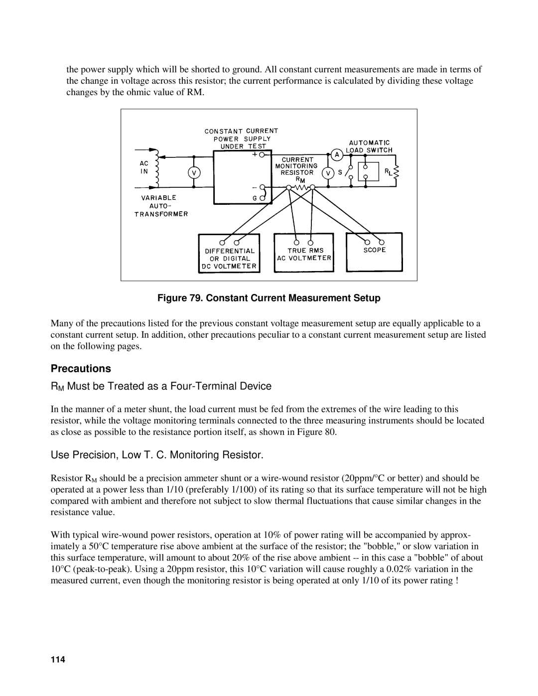
the power supply which will be shorted to ground. All constant current measurements are made in terms of the change in voltage across this resistor; the current performance is calculated by dividing these voltage changes by the ohmic value of RM.
Figure 79. Constant Current Measurement Setup
Many of the precautions listed for the previous constant voltage measurement setup are equally applicable to a constant current setup. In addition, other precautions peculiar to a constant current measurement setup are listed on the following pages.
Precautions
RM Must be Treated as a Four-Terminal Device
In the manner of a meter shunt, the load current must be fed from the extremes of the wire leading to this resistor, while the voltage monitoring terminals connected to the three measuring instruments should be located as close as possible to the resistance portion itself, as shown in Figure 80.
Use Precision, Low T. C. Monitoring Resistor.
Resistor RM should be a precision ammeter shunt or a
With typical
114