Agilent Technologies 90B manual Automatic Load Switch for Measuring Transient Recovery Time

Models: 90B

1 125
Download 125 pages 25.51 Kb
Page 109
Image 109

transient recovery time of a power supply, the spike amplitude for load switching times of less than 1 microsecond cannot be accurately determined, unless a very wideband scope is used.

Of all power supply specifications, transient recovery time is subject to the widest variation in definition, and is not defined at all by some power supply manufacturers. Specifying that a power supply has a transient recovery time of "50 microseconds" is incomplete and conveys no information. Such a specification leaves to the imagination whether the power supply will recover during the 50∝ second interval to within 37% (1/e) of its initial value, to within 10%, or "all the way."

Since the falling portion of the transient remains reasonable constant in spite of wide variations in the spike amplitude and the speed of the load change causing it, Agilent Technologies has chosen to define transient recovery time in terms of recovery to a certain voltage level. For ease in oscilloscope measurement, this voltage level is referenced to a nominal output voltage half-way between no load and full load.

Reasonable care must be taken in switching the load resistance on and off. A hand-operated switch in series with the load is not adequate, since the resulting one-shot displays are difficult to observe on most oscilloscopes, and the arc energy occurring during switching action completely masks the display with a noise burst. Transistor load switching devices are expensive if reasonably rapid load current changes are to be achieved.

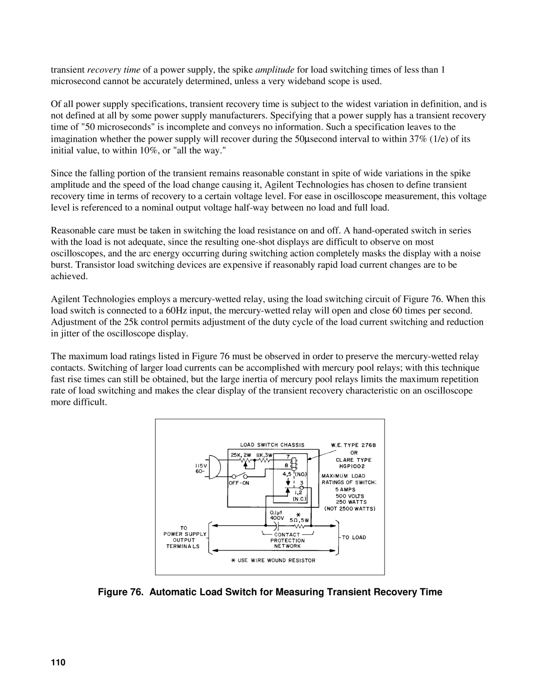
Agilent Technologies employs a mercury-wetted relay, using the load switching circuit of Figure 76. When this load switch is connected to a 60Hz input, the mercury-wetted relay will open and close 60 times per second. Adjustment of the 25k control permits adjustment of the duty cycle of the load current switching and reduction in jitter of the oscilloscope display.

The maximum load ratings listed in Figure 76 must be observed in order to preserve the mercury-wetted relay contacts. Switching of larger load currents can be accomplished with mercury pool relays; with this technique fast rise times can still be obtained, but the large inertia of mercury pool relays limits the maximum repetition rate of load switching and makes the clear display of the transient recovery characteristic on an oscilloscope more difficult.

Figure 76. Automatic Load Switch for Measuring Transient Recovery Time

110

Page 109
Image 109
Agilent Technologies 90B manual Automatic Load Switch for Measuring Transient Recovery Time