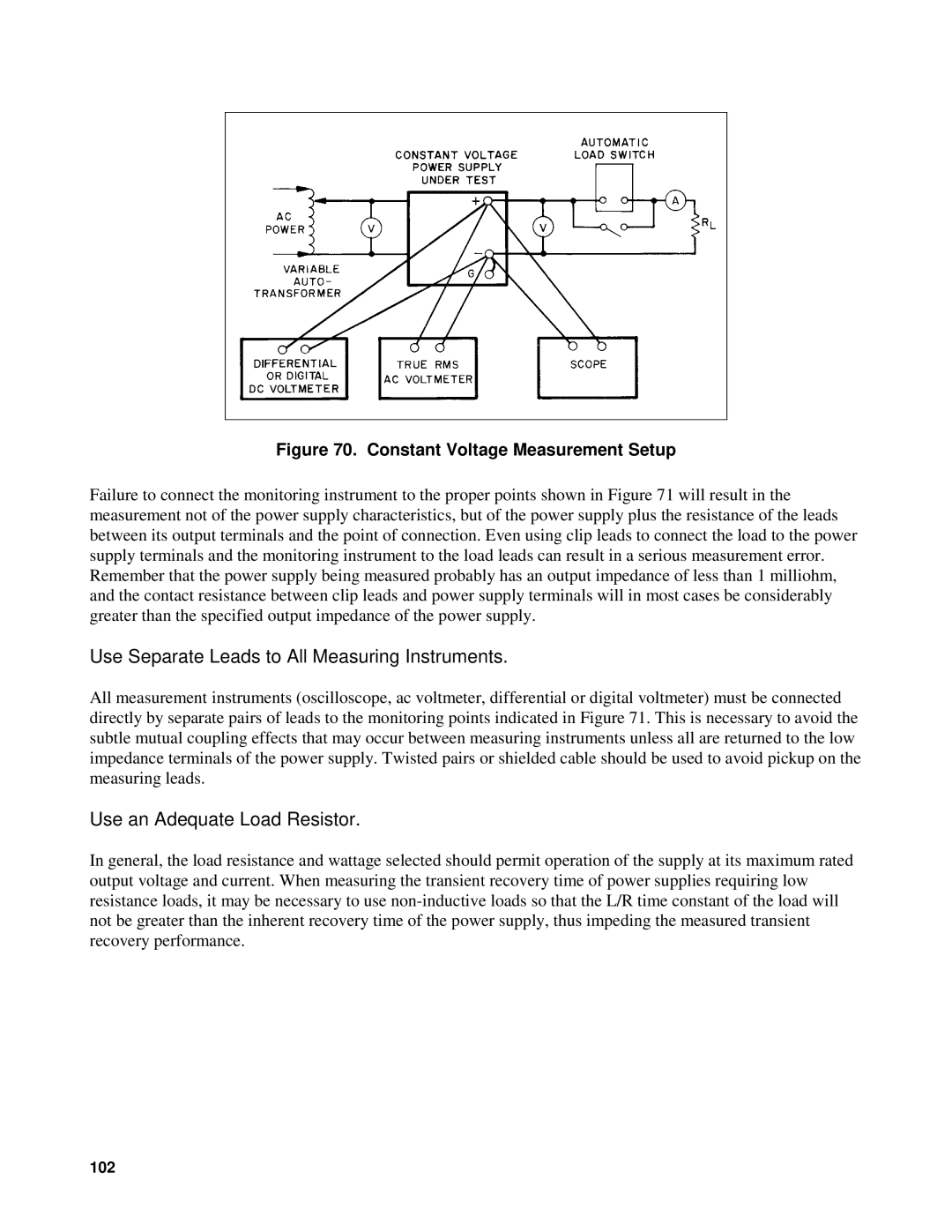
Figure 70. Constant Voltage Measurement Setup
Failure to connect the monitoring instrument to the proper points shown in Figure 71 will result in the measurement not of the power supply characteristics, but of the power supply plus the resistance of the leads between its output terminals and the point of connection. Even using clip leads to connect the load to the power supply terminals and the monitoring instrument to the load leads can result in a serious measurement error. Remember that the power supply being measured probably has an output impedance of less than 1 milliohm, and the contact resistance between clip leads and power supply terminals will in most cases be considerably greater than the specified output impedance of the power supply.
Use Separate Leads to All Measuring Instruments.
All measurement instruments (oscilloscope, ac voltmeter, differential or digital voltmeter) must be connected directly by separate pairs of leads to the monitoring points indicated in Figure 71. This is necessary to avoid the subtle mutual coupling effects that may occur between measuring instruments unless all are returned to the low impedance terminals of the power supply. Twisted pairs or shielded cable should be used to avoid pickup on the measuring leads.
Use an Adequate Load Resistor.
In general, the load resistance and wattage selected should permit operation of the supply at its maximum rated output voltage and current. When measuring the transient recovery time of power supplies requiring low resistance loads, it may be necessary to use
102