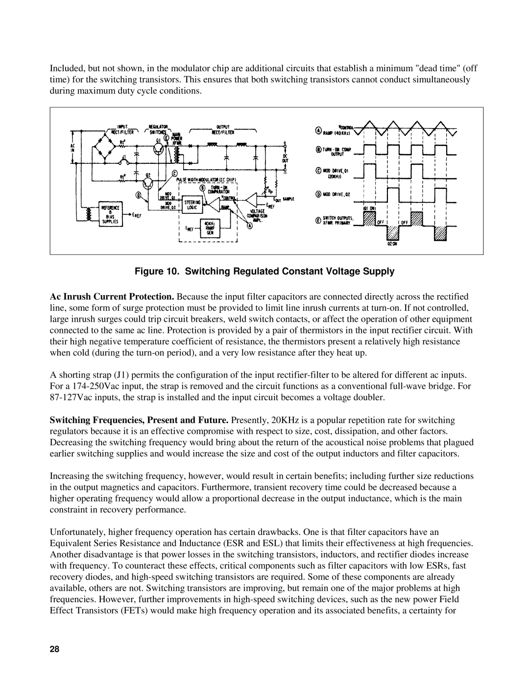
Included, but not shown, in the modulator chip are additional circuits that establish a minimum "dead time" (off time) for the switching transistors. This ensures that both switching transistors cannot conduct simultaneously during maximum duty cycle conditions.
Figure 10. Switching Regulated Constant Voltage Supply
Ac Inrush Current Protection. Because the input filter capacitors are connected directly across the rectified line, some form of surge protection must be provided to limit line inrush currents at
A shorting strap (J1) permits the configuration of the input
Switching Frequencies, Present and Future. Presently, 20KHz is a popular repetition rate for switching regulators because it is an effective compromise with respect to size, cost, dissipation, and other factors. Decreasing the switching frequency would bring about the return of the acoustical noise problems that plagued earlier switching supplies and would increase the size and cost of the output inductors and filter capacitors.
Increasing the switching frequency, however, would result in certain benefits; including further size reductions in the output magnetics and capacitors. Furthermore, transient recovery time could be decreased because a higher operating frequency would allow a proportional decrease in the output inductance, which is the main constraint in recovery performance.
Unfortunately, higher frequency operation has certain drawbacks. One is that filter capacitors have an Equivalent Series Resistance and Inductance (ESR and ESL) that limits their effectiveness at high frequencies. Another disadvantage is that power losses in the switching transistors, inductors, and rectifier diodes increase with frequency. To counteract these effects, critical components such as filter capacitors with low ESRs, fast recovery diodes, and
28