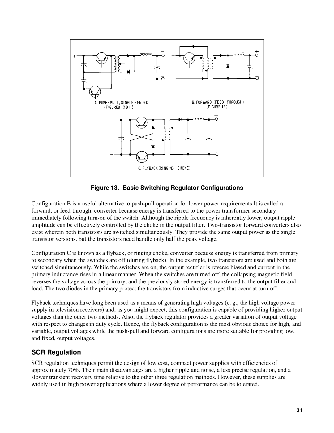
Figure 13. Basic Switching Regulator Configurations
Configuration B is a useful alternative to
Configuration C is known as a flyback, or ringing choke, converter because energy is transferred from primary to secondary when the switches are off (during flyback). In the example, two transistors are used and both are switched simultaneously. While the switches are on, the output rectifier is reverse biased and current in the primary inductance rises in a linear manner. When the switches are turned off, the collapsing magnetic field reverses the voltage across the primary, and the previously stored energy is transferred to the output filter and load. The two diodes in the primary protect the transistors from inductive surges that occur at
Flyback techniques have long been used as a means of generating high voltages (e. g., the high voltage power supply in television receivers) and, as you might expect, this configuration is capable of providing higher output voltages than the other two methods. Also, the flyback regulator provides a greater variation of output voltage with respect to changes in duty cycle. Hence, the flyback configuration is the most obvious choice for high, and variable, output voltages while the
SCR Regulation
SCR regulation techniques permit the design of low cost, compact power supplies with efficiencies of approximately 70%. Their main disadvantages are a higher ripple and noise, a less precise regulation, and a slower transient recovery time relative to the other three regulation methods. However, these supplies are widely used in high power applications where a lower degree of performance can be tolerated.
31