to variations of the line and load. Hence, their line and load regulation and transient recovery time* are superior to supplies using any of the other regulation techniques. These supplies also exhibit the lowest ripple and noise, are tolerant of ambient temperature changes, and with their circuit simplicity, have a high reliability.
*Power supply performance specifications are described in the Definitions section of this handbook.
The major drawback of the series regulated supply is its relatively low efficiency. This is caused mainly by the series transistor which, operating in the linear mode, continuously dissipates power in carrying out its regulation function. Efficiency (defined as the percentage of a supply's input power that it can deliver as useful output: POUT/PIN), ranges typically between 30 and 45% for series regulated supplies. With the present need for energy conservation, this inefficiency is being scrutinized very closely.
For many of today's applications, the size and weight of linear supplies constitute another disadvantage. The power transformer, inductors, and filter capacitors necessary for operation at the 60Hz line frequency tend to be large and heavy, and the heat sink required for the inherently dissipative series regulator increases the overall size.
The Series Regulated Supply - An Operational Amplifier
The following analogy views the series regulated power supply as an operational amplifier. Considering the power supply as an operational amplifier can often give the user a quick insight into power supply behavior and help in evaluating a power supply for a specific application.
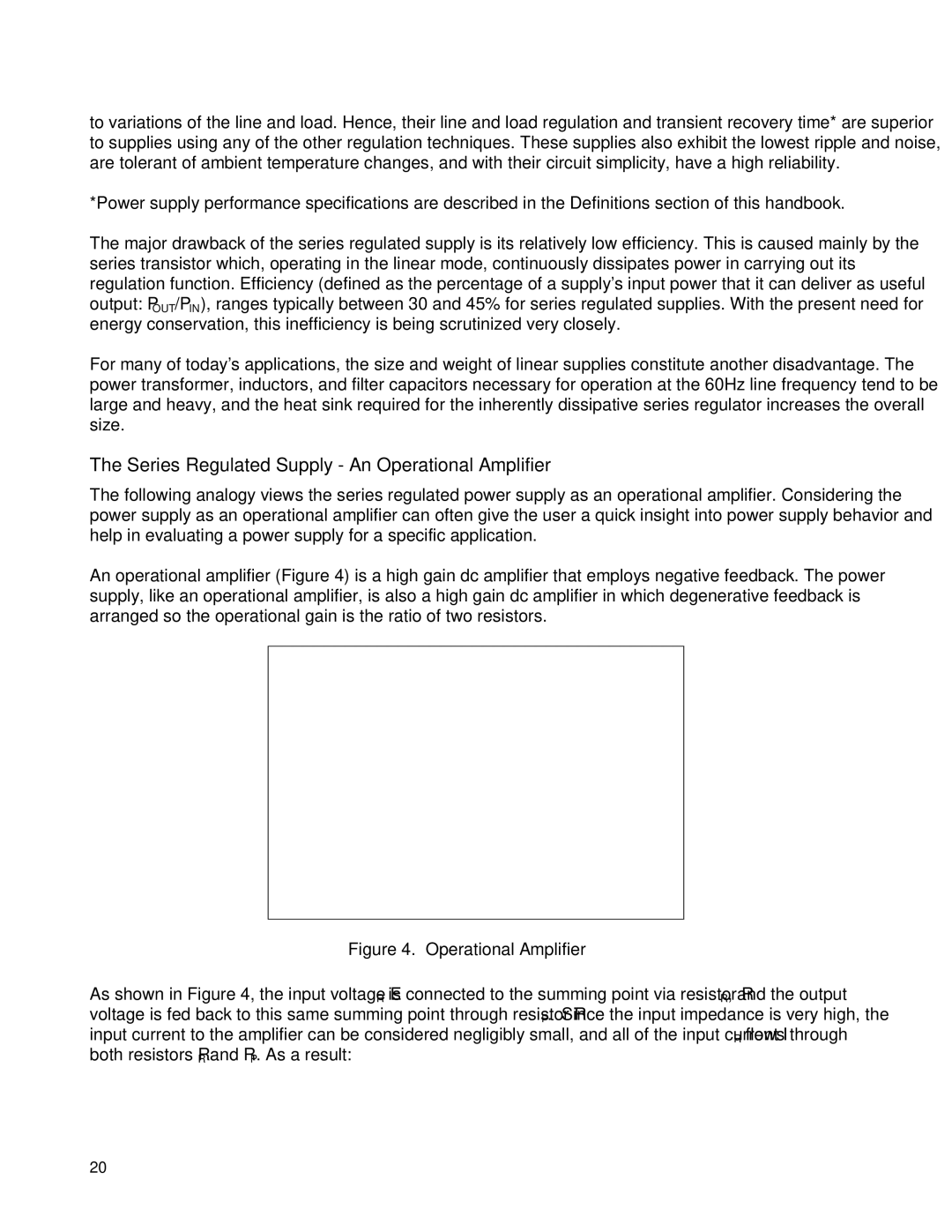
An operational amplifier (Figure 4) is a high gain dc amplifier that employs negative feedback. The power supply, like an operational amplifier, is also a high gain dc amplifier in which degenerative feedback is arranged so the operational gain is the ratio of two resistors.
Figure 4. Operational Amplifier
As shown in Figure 4, the input voltage ER is connected to the summing point via resistor RR, and the output voltage is fed back to this same summing point through resistor RP. Since the input impedance is very high, the input current to the amplifier can be considered negligibly small, and all of the input current IR flows through both resistors RR and RP. As a result:
20