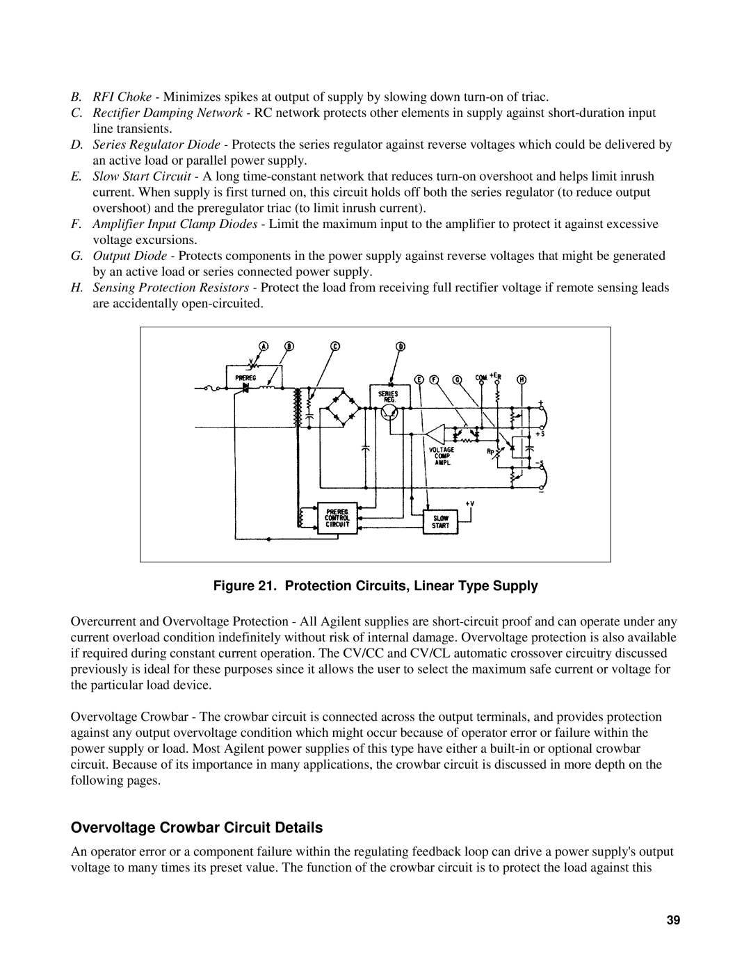
B.RFI Choke - Minimizes spikes at output of supply by slowing down
C.Rectifier Damping Network - RC network protects other elements in supply against
D.Series Regulator Diode - Protects the series regulator against reverse voltages which could be delivered by an active load or parallel power supply.
E.Slow Start Circuit - A long
F.Amplifier Input Clamp Diodes - Limit the maximum input to the amplifier to protect it against excessive voltage excursions.
G.Output Diode - Protects components in the power supply against reverse voltages that might be generated by an active load or series connected power supply.
H.Sensing Protection Resistors - Protect the load from receiving full rectifier voltage if remote sensing leads are accidentally
Figure 21. Protection Circuits, Linear Type Supply
Overcurrent and Overvoltage Protection - All Agilent supplies are
Overvoltage Crowbar - The crowbar circuit is connected across the output terminals, and provides protection against any output overvoltage condition which might occur because of operator error or failure within the power supply or load. Most Agilent power supplies of this type have either a
Overvoltage Crowbar Circuit Details
An operator error or a component failure within the regulating feedback loop can drive a power supply's output voltage to many times its preset value. The function of the crowbar circuit is to protect the load against this
39