Quick Start: Learning How to Make Measurements
Learning to Make Reflection Measurements
Learning to Make Reflection Measurements
This example procedure shows you how to measure the reflection response of a 10.24 GHz bandpass filter. The measurement parameter values listed are unique to this particular test device.
For further measurement examples, refer to the "Making Measurements" chapter in the User's Guide.
NOTE | Reflection measurements monitor only one port of a test device. When a test |
| device has more than one port, you must ensure that the unused port(s) are |
| terminated in their characteristic impedance (for example, 50Ω or 75Ω). If |
| you do not terminate unused ports, reflections from these ports will cause |
| measurement errors. Figure |
| terminate an unused device port with the proper characteristic impedance. |
|
|
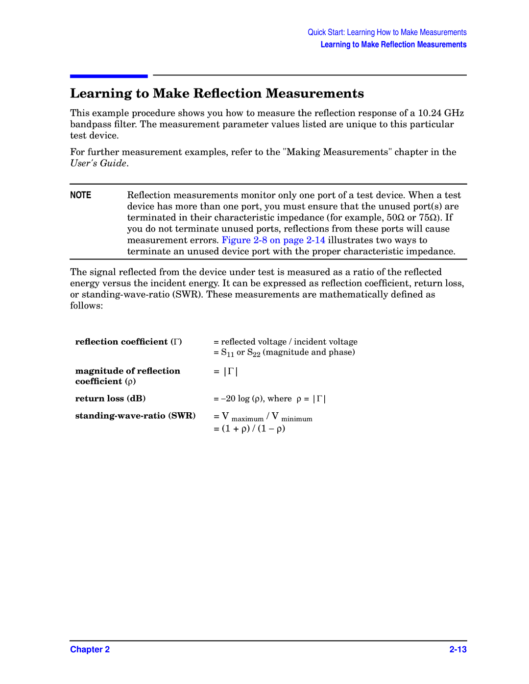
The signal reflected from the device under test is measured as a ratio of the reflected energy versus the incident energy. It can be expressed as reflection coefficient, return loss, or
reflection coefficient (Γ) | = reflected voltage / incident voltage |
| = S11 or S22 (magnitude and phase) |
magnitude of reflection | = Γ |
coefficient (ρ) |
|
return loss (dB) | = −20 log (ρ), where ρ = Γ |
= V maximum / V minimum | |
| = (1 + ρ) / (1 − ρ) |
Chapter 2 |
