NetExtreme Family Adapters
Page
Electrical Safety and Emissions Standards
Translated Safety Statements
Contents
Selecting the Advanced Tab in Windows Server
Using the Silent Install Option
Contents
Figures
Figures
Preface
Symbol Meaning Description
Safety Symbols Used in this Document
Where to Find Web-based Guides
Allied Telesis FTP serverftp//ftp.alliedtelesis.com
Management Software Updates
Contacting Allied Telesis
Chapter
Introducing the AT-2973SX, AT-2973T, and AT-2973T/4 Adapters
Functional Descriptions
AT-2973SX Adapter Physical Description
AT-2973SX Adapter
Port LED LED Appearance Network State
AT-2973T Adapter
AT-2973T Adapter Physical Description
Port LED LED Appearance Network State
ATI
AT-2973T/4 Adapter
AT-2973T/4 Faceplate
AT-2973T/4 Adapter Physical Description
Features
TCP Offload Engine TOE
Wake on LAN WOL Feature
MS-DOS
Introducing the AT-2973SX, AT-2973T, and AT-2973T/4 Adapters
Installing the Hardware
Reviewing the Contents of Your Shipment
Reviewing Safety Precautions
Installing the Hardware
Pre-Installation Checklist
Removing the Low-Profile Bracket
Replacing the Bracket
Fastening Screws onto Standard Bracket
Installing a Network Adapter Card
Page
Installing the Hardware
Page
Connecting the Network Cables
Page
Installing the Hardware
Installing Broadcom Boot Agent Driver Software
Overview
Configuring the MBA Driver
Setting Up MBA in a Client Environment
Uxdiag -mba 0-disable 1-enable -c devnum where
Enabling the MBA Driver
Bios
Setting Up
Images/pxeboot/vmlinuz Images/pxeboot/initrd.img
Installing Broadcom Boot Agent Driver Software
Installing the Monolithic Software Driver
Using the NetXtreme II Monolithic Driver
Page
For example copype x86 c\VistaPEx86
Copype.cmd arch destination
Yes
Imagex /mountrw c\VistaPEx86\winpe.wim 1 c\VistaPEx86\mount
Peimg /prep c\VistaPEx86\mount\windows
Paramsutp Hkr, , reqmedium Paramsfiber
Configuring the Speed and Duplex Settings
Page
Installing the Monolithic Software Driver
Installing the NDIS2 Driver Software
Overview
Checking Pre-installation Requirements
Creating a Startup Disk
Installing the NDIS2 Driver Software on MS-DOS Platforms
Enter the following expand -r ncadmin
Modifying the Startup Disk
Network.setup Version=0x3110
Example Protocol.ini file for IP
Example Protocol.ini file for NetBEUI
Example system.ini file
Change netcard= to netcard=BXND20X.dos
NetBEUI
Installing
Driver Software
DriverName = BXND20X$
Bindings = BXND20X BXND20X
Using Keywords for the Drivers
BXND20X
Installing the Linux Drivers
Linux Driver Description
Bnx2 Driver
Format
Bnx2i Driver
Bnx2 Driver Bnx2i iSCSI Driver
Rpm -ivh netxtreme2-version.src.rpm
Installing Linux Driver Software
Installing Source RPM Package
Kernels and newer bnx2i driver
Kernels
Kernels and newer bnx2 driver
Cd bnx2-version/src make
Building the Driver from the Source TAR File
Building the bnx2 Driver
Building the bnx2i Driver
Cd $DRVBASE/driver make installusr
Tar xvzf bnx2-version.tar.gz
Cd bnx2i-version/drivermake
Bnx2id Insmod bnx2i.ko or Modprobe bnx2i
Unloading the Driver from an RPM Installation
Rmmod bnx2i pkill -9 bnx2id
Patching PCI Files Optional
Unloading the Driver from a TAR Installation
Rmmod bnx2
Rpm -e netxtreme2
Setting Values for Optional Properties
Network Installations
Setting Optional Properties for the bnx2i Driver
Setting Optional Properties for the bnx2 Driver
Insmod bnx2.ko disablemsi=1 Modprobe bnx2 disablemsi=1
Errormask1 and errormask2
Insmod bnx2i.ko entcpdack=0 Modprobe bnx2i entcpdack=0
Entcpdack
Sqsize
Rqsize
Checking Bnx2 Driver Defaults
Checking the bnx2 Driver Messages
Checking Driver Messages
Driver Sign on
Cnic Driver Sign on
Link Up and Speed Indication
MSI enabled successfully bnx2 only
Link Down Indication
Checking bnx2i Driver Messages
Target cannot be reached on any of the Cnic devices
SCSI-ML initiated host reset session recovery
Cnic detects iSCSI protocol violation Fatal errors
Connerr hostno 3 conn 03fbcd00, iscsicid 2 cid a1800
Driver puts a session through recovery
Cnic detects iSCSI protocol violation non-FATAL, warning
Teaming with Channel Bonding Statistics Linux iSCSI Offload
Bnx2i conn update MBL 0x800 FBL 0x800MRDSLI 0x800 Mrdslt
Reject iSCSI PDU received from the target
Open-iSCSI daemon handing over session to driver
Installing Open iSCSI User Applications
Installing User Application bnx2id
Dmesg grep bnx2i netif
Binding iSCSI Target to Broadcom NX2 iSCSI Transport Name
Rpm -ivh RPMS/i386/open-iscsi-package- name.i386.rpm
Maximizing Offload iSCSI Connections
Making Connections to iSCSI Targets
Installing the Linux Drivers
Installing the Windows Drivers
Installing the Windows Driver Software
See on page 90 for the Found New Hardware Wizard
Using the Installer
Installing the Windows Drivers
Page
Installing the Windows Drivers
Page
InstallShield Wizard Completed
Using Silent Installation
Performing a Silent Install and Creating a Log File
Performing a Silent Install
Performing a Silent Upgrade
Performing a Silent Uninstall
Setup /s /v/qn REINSTALL=ALL
Performing a Silent Reinstall
Msiexec /x BDrv5706.msi /qn
Msiexec /x F0DA8A3F-1457-419E-96F4-235DD3EF41E1 / qn
Removing the Device Drivers
Installing the Windows Drivers
Setting Advanced Properties
Selecting Advanced Tab Windows Server 2003
Accessing the Advanced Tab
101
Advanced Tab
103
Selecting Advanced Tab Windows Vista
Windows Vista Run Window
106
Modifying Advanced Properties
Updating Ethernet@ WireSpeed Property Flow Control
109
Updating Interrupt Moderation Property
Enabled Disabled
Updating Checksum Offload Property
IPv4 Large Send Offload IPv6 Large Send Offload
Updating Large Send Offload Property
Updating Jumbo MTU Property
Updating Network Address Property
Auto, 1, 2, 4, 8, or 16 for 10 Gbps adapters
Updating the RSS Queues Property
Updating Priority & Vlan Property
117
Updating Speed & Duplex Mode Property
10 Mb Full 10 Mb Half 100 Mb Full 100 Mb Half Auto
Updating TCP Connection Offload Properties
Vlan ID
Updating Transmit Buffers Property
122
Installing CIM and Snmp for Manageability
Installing CIM
Loading the CIM Libraries
126
Basp Extensible- Agent
Installing Snmp
Basp Subagent
Loading the Snmp Libraries
Select Snmp Bacs Snmp Option Window is displayed. See Figure
Installing CIM and Snmp for Manageability 130
Installing Management Applications
132
Checking .NET Framework Requirements
Using the Silent Install Option
Using Installer
Setup /s /v/qn REBOOT=ReallySuppress
Performing a Silent Install from any Folder
Setup /s /v/qn /L f\ia32\1testlog.txt
Msiexec /x 26E1BFB0-E87E-4696-9F89-B467F01F81E5 / qn
Start /wait setup /s /w /v/qn
Performing a Silent Install by Feature on IA32 Platforms
Performing a Silent Install from Within a Batch File
Click Broadcom Management Programs and then click Change
Modifying Management Applications
Click Broadcom Management Programs, and then click Change
Repairing Management Applications
Click Broadcom Management Programs, and then click Remove
Removing Management Applications
Installing Management Applications 140
Troubleshooting
Checking Hardware Diagnostics
Checking Port LEDs
Windows
Consulting the Troubleshooting Checklist
Checking Current Drivers
Linux
Running a Cable Length Test Testing Network Connectivity
Lsmod
Module Size Used by BCM5709
146
Single Network Adapter Teamed Network Adapters
Solving Microsoft Windows Server 2008 R2 Hyper-V Issues
Removing the Device Drivers
OemPreinstall=Yes OemPnpDriversPath=Drivers\NIC
149
150
151
Solving Miscellaneous Issues
153
Troubleshooting 154
User Diagnostics
156
System Requirements
\uxdiag -c 1 -t b
Performing Diagnostics
Command Options Description
= PXE
160
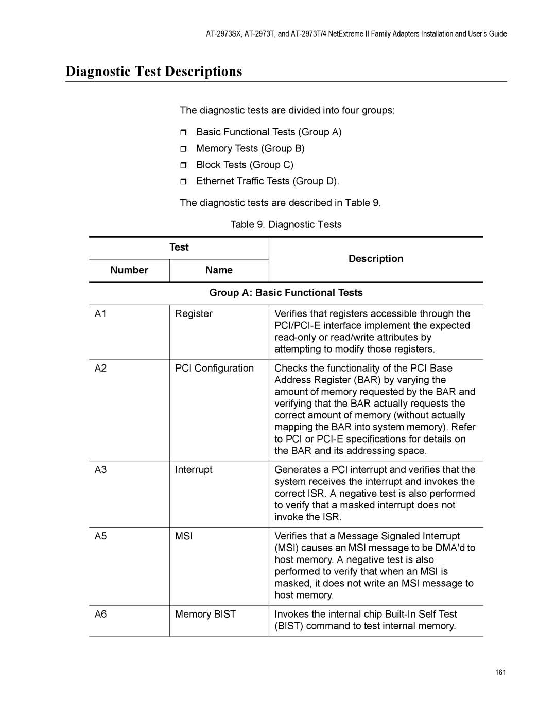
Test Description Number Name Group a Basic Functional Tests
Diagnostic Test Descriptions
Test Description Number Name
163
Group D Ethernet Traffic Tests
VPD
LSO
User Diagnostics 166
Physical Specifications
Specifications
Environmental Specifications
Appendix a
Performance Specifications
Power Specifications
Operating Specifications
10/100/1000Base-T Twisted-Pair Port Connectors
Pin Pair Signal
Appendix a Specifications 170
Appendix B
Cleaning Fiber Optic Connectors
Rubbing the Ferrule Tip on the Cleaning Surface
Using a Cartridge-Type Cleaner
173
Cleaning a Recessed Ferrule If desired, repeat step
Using a Swab
175
Appendix B Cleaning Fiber Optic Connectors 176