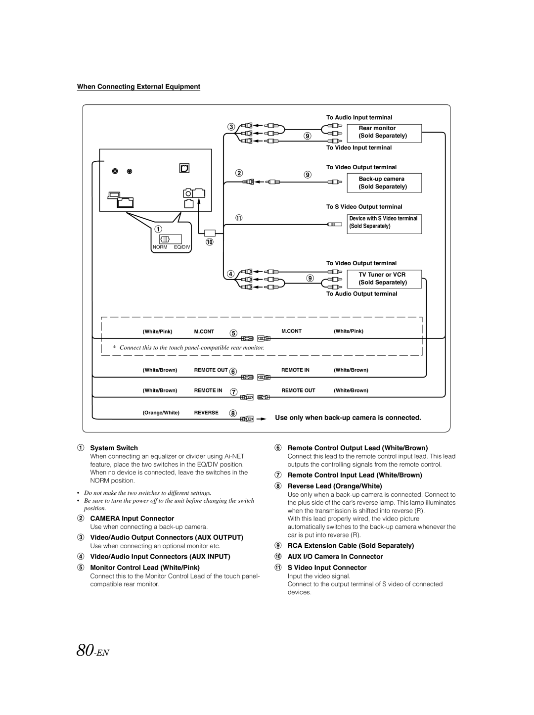
When Connecting External Equipment
To Audio Input terminal
Rear monitor (Sold Separately)
To Video Input terminal
To Video Output terminal
To S Video Output terminal
Device with S Video terminal (Sold Separately)
NORM EQ/DIV
To Video Output terminal
TV Tuner or VCR (Sold Separately)
To Audio Output terminal
(White/Pink) | M.CONT | M.CONT | (White/Pink) |
* Connect this to the touch
(White/Brown) | REMOTE OUT |
(White/Brown) | REMOTE IN |
(Orange/White) | REVERSE |
System Switch
When connecting an equalizer or divider using
•Do not make the two switches to different settings.
•Be sure to turn the power off to the unit before changing the switch position.
CAMERA Input Connector
Use when connecting a
Video/Audio Output Connectors (AUX OUTPUT)
Use when connecting an optional monitor etc.
Video/Audio Input Connectors (AUX INPUT)
Monitor Control Lead (White/Pink)
Connect this to the Monitor Control Lead of the touch panel- compatible rear monitor.
REMOTE IN | (White/Brown) |
REMOTE OUT | (White/Brown) |
Use only when
Remote Control Output Lead (White/Brown)
Connect this lead to the remote control input lead. This lead outputs the controlling signals from the remote control.
Remote Control Input Lead (White/Brown)
Reverse Lead (Orange/White)
Use only when a
With this lead properly wired, the video picture automatically switches to the
RCA Extension Cable (Sold Separately)
AUX I/O Camera In Connector
S Video Input Connector
Input the video signal.
Connect to the output terminal of S video of connected devices.