AMD Sempron™ Processor Model 10 with 256K L2 Cache Data Sheet
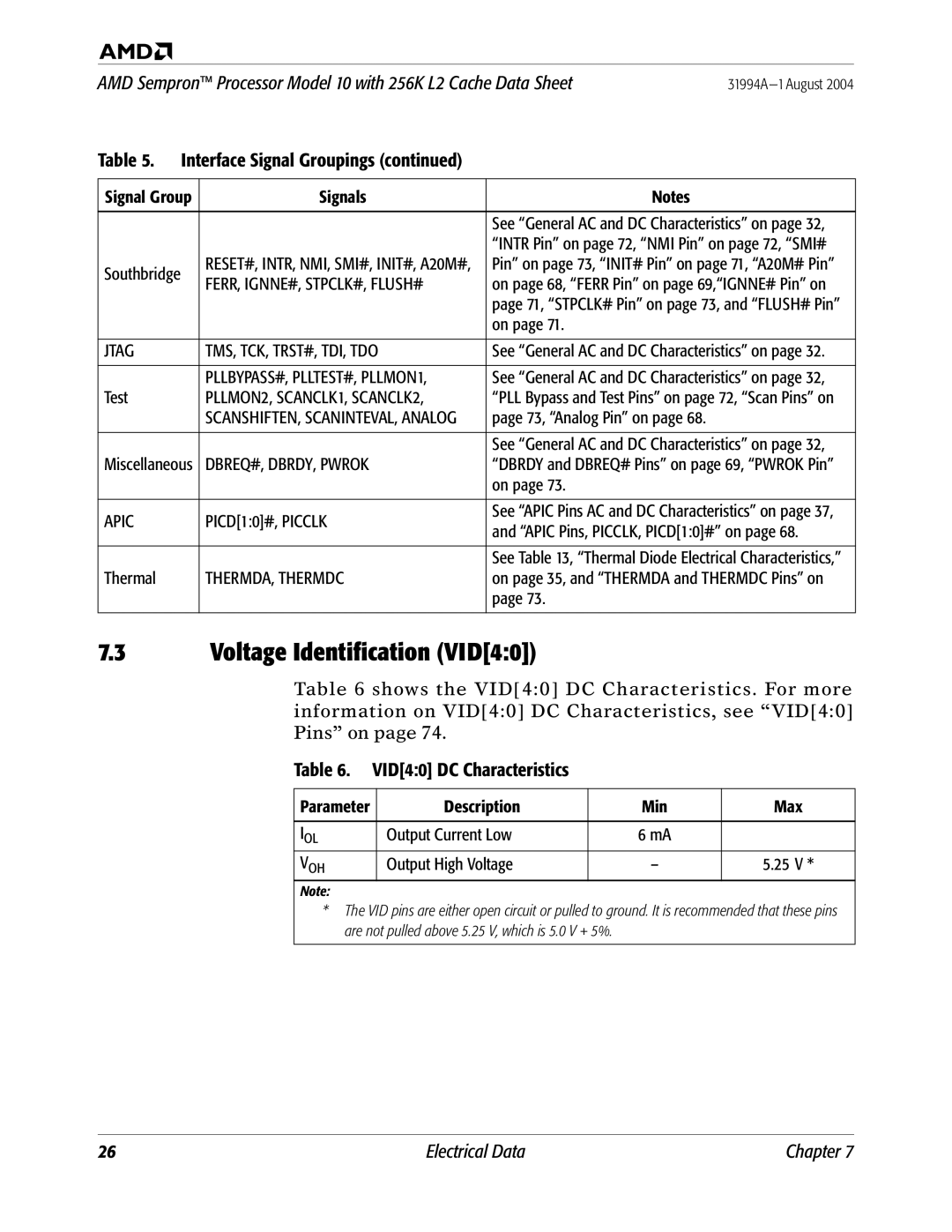
Table 5. Interface Signal Groupings (continued)
Signal Group | Signals | Notes | |
|
|
| |
|
| See “General AC and DC Characteristics” on page 32, | |
|
| “INTR Pin” on page 72, “NMI Pin” on page 72, “SMI# | |
Southbridge | RESET#, INTR, NMI, SMI#, INIT#, A20M#, | Pin” on page 73, “INIT# Pin” on page 71, “A20M# Pin” | |
FERR, IGNNE#, STPCLK#, FLUSH# | on page 68, “FERR Pin” on page 69,“IGNNE# Pin” on | ||
| |||
|
| page 71, “STPCLK# Pin” on page 73, and “FLUSH# Pin” | |
|
| on page 71. | |
|
|
| |
JTAG | TMS, TCK, TRST#, TDI, TDO | See “General AC and DC Characteristics” on page 32. | |
|
|
| |
| PLLBYPASS#, PLLTEST#, PLLMON1, | See “General AC and DC Characteristics” on page 32, | |
Test | PLLMON2, SCANCLK1, SCANCLK2, | “PLL Bypass and Test Pins” on page 72, “Scan Pins” on | |
| SCANSHIFTEN, SCANINTEVAL, ANALOG | page 73, “Analog Pin” on page 68. | |
|
|
| |
|
| See “General AC and DC Characteristics” on page 32, | |
Miscellaneous | DBREQ#, DBRDY, PWROK | “DBRDY and DBREQ# Pins” on page 69, “PWROK Pin” | |
|
| on page 73. | |
|
|
| |
APIC | PICD[1:0]#, PICCLK | See “APIC Pins AC and DC Characteristics” on page 37, | |
and “APIC Pins, PICCLK, PICD[1:0]#” on page 68. | |||
|
| ||
|
|
| |
|
| See Table 13, “Thermal Diode Electrical Characteristics,” | |
Thermal | THERMDA, THERMDC | on page 35, and “THERMDA and THERMDC Pins” on | |
|
| page 73. | |
|
|
|
7.3 | Voltage Identification (VID[4:0]) |
|
| ||||
|
| Table 6 shows the VID[4:0] DC Characteristics. For more | |||||
|
| information on VID[4:0] DC Characteristics, see “VID[4:0] | |||||
|
| Pins” on page 74. |
|
| |||
|
| Table 6. | VID[4:0] DC Characteristics |
|
| ||
|
|
|
|
|
|
|
|
|
| Parameter |
| Description |
| Min | Max |
|
|
|
|
|
|
|
|
|
| IOL |
| Output Current Low |
| 6 mA |
|
|
| VOH |
| Output High Voltage |
| – | 5.25 V * |
|
| Note: |
|
|
|
|
|
|
| * The VID pins are either open circuit or pulled to ground. It is recommended that these pins | |||||
|
| are not pulled above 5.25 V, which is 5.0 V + 5%. |
|
| |||
|
|
|
|
|
|
|
|
26 | Electrical Data | Chapter 7 |