31994A | AMD Sempron™ Processor Model 10 with 256K L2 Cache Data Sheet |
7.9SYSCLK and SYSCLK# DC Characteristics
Table 11 shows the DC characteristics of the SYSCLK and SYSCLK# differential clocks. The SYSCLK signal represents CLKIN and RSTCLK tied together while the SYSCLK# signal represents CLKIN# and RSTCLK# tied together. For more information about SYSCLK and SYSCLK#, see “SYSCLK and SYSCLK#” on page 73 and Table 19, “Pin Name Abbreviations,” on page 52.
Table 11. SYSCLK and SYSCLK# DC Characteristics
Symbol | Description | Min | Max | Units | |
|
|
|
|
|
|
Crossing before transition is detected (DC) | 400 |
|
| mV | |
Crossing before transition is detected (AC) | 450 |
|
| mV | |
ILEAK_P | Leakage current through |
|
| mA | |
ILEAK_N | Leakage current through |
| 1 |
| mA |
VCROSS | Differential signal crossover |
| VCC_CORE | ± 100 | mV |
| |||||
|
|
| 2 |
|
|
|
|
|
|
| |
CPIN | Capacitance * | 4 | 25 * | pF | |
Note:
* The following processor inputs have twice the listed capacitance because they connect to two input
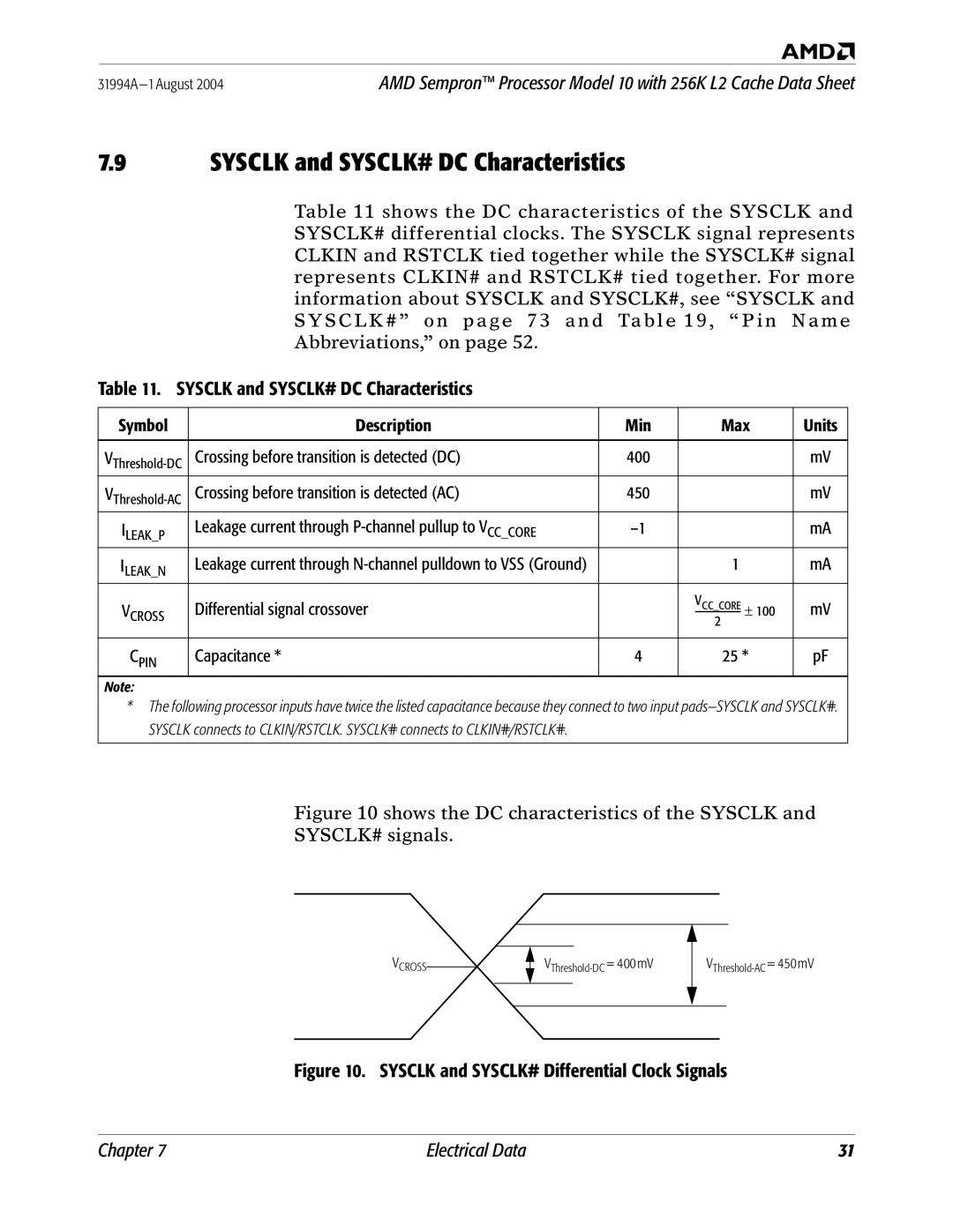
Figure 10 shows the DC characteristics of the SYSCLK and
SYSCLK# signals.
VCROSS
Figure 10. SYSCLK and SYSCLK# Differential Clock Signals
Chapter 7 | Electrical Data | 31 |