31994A | AMD Sempron™ Processor Model 10 with 256K L2 Cache Data Sheet |
7.12Thermal Diode Characteristics
| The AMD Sempron processor model 10 provides a diode that | |||||||
| can be used in conjunction with an external temperature sensor | |||||||
| to determine the die temperature of the processor. The diode | |||||||
| anode (THERMDA) and cathode (THERMDC) are available as | |||||||
| pins on the processor, as described in “THERMDA and | |||||||
| THERMDC Pins” on page 73. |
|
|
|
|
| ||
| For information about thermal design for the AMD Sempron | |||||||
| processor model 10, including layout and airflow | |||||||
| considerations, see the AMD Processor Thermal, Mechanical, and | |||||||
| Chassis Cooling Design Guide, order# 23794, and the cooling | |||||||
| guidelines on http://www.amd.com. |
|
|
|
| |||
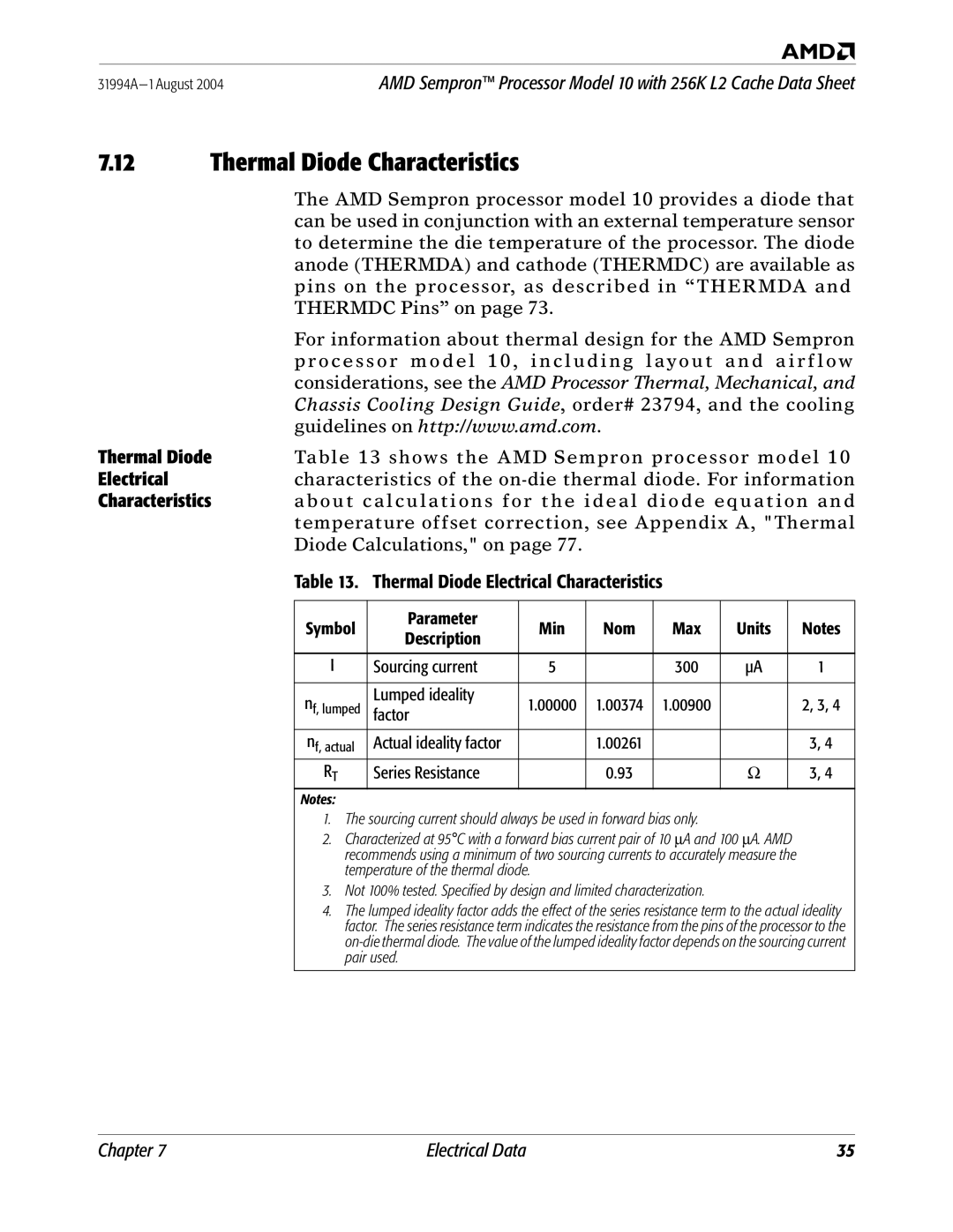
Thermal Diode | Table 13 shows the AMD Sempron processor model 10 | |||||||
Electrical | characteristics of the | |||||||
Characteristics | about calculations for the ideal diode equation and | |||||||
| temperature offset correction, see Appendix A, "Thermal | |||||||
| Diode Calculations," on page 77. |
|
|
|
|
| ||
| Table 13. Thermal Diode Electrical Characteristics |
|
|
| ||||
|
|
|
|
|
|
|
|
|
| Symbol | Parameter | Min | Nom | Max | Units |
| Notes |
| Description |
| ||||||
|
|
|
|
|
|
|
| |
|
|
|
|
|
|
|
|
|
| I | Sourcing current | 5 |
| 300 | µA |
| 1 |
|
|
|
|
|
|
|
|
|
| nf, lumped | Lumped ideality | 1.00000 | 1.00374 | 1.00900 |
|
| 2, 3, 4 |
| factor |
|
| |||||
|
|
|
|
|
|
|
| |
|
|
|
|
|
|
|
|
|
| nf, actual | Actual ideality factor |
| 1.00261 |
|
|
| 3, 4 |
| RT | Series Resistance |
| 0.93 |
| Ω |
| 3, 4 |
| Notes: |
|
|
|
|
|
|
|
| 1. The sourcing current should always be used in forward bias only. |
|
|
| ||||
| 2. Characterized at 95°C with a forward bias current pair of 10 ∝A and 100 ∝A. AMD |
| ||||||
| recommends using a minimum of two sourcing currents to accurately measure the |
| ||||||
| temperature of the thermal diode. |
|
|
|
|
| ||
| 3. Not 100% tested. Specified by design and limited characterization. |
|
|
| ||||
| 4. The lumped ideality factor adds the effect of the series resistance term to the actual ideality | |||||||
| factor. The series resistance term indicates the resistance from the pins of the processor to the | |||||||
| ||||||||
| pair used. |
|
|
|
|
|
| |
|
|
|
|
|
|
|
|
|
Chapter 7 | Electrical Data | 35 |