31994A | AMD Sempron™ Processor Model 10 with 256K L2 Cache Data Sheet |
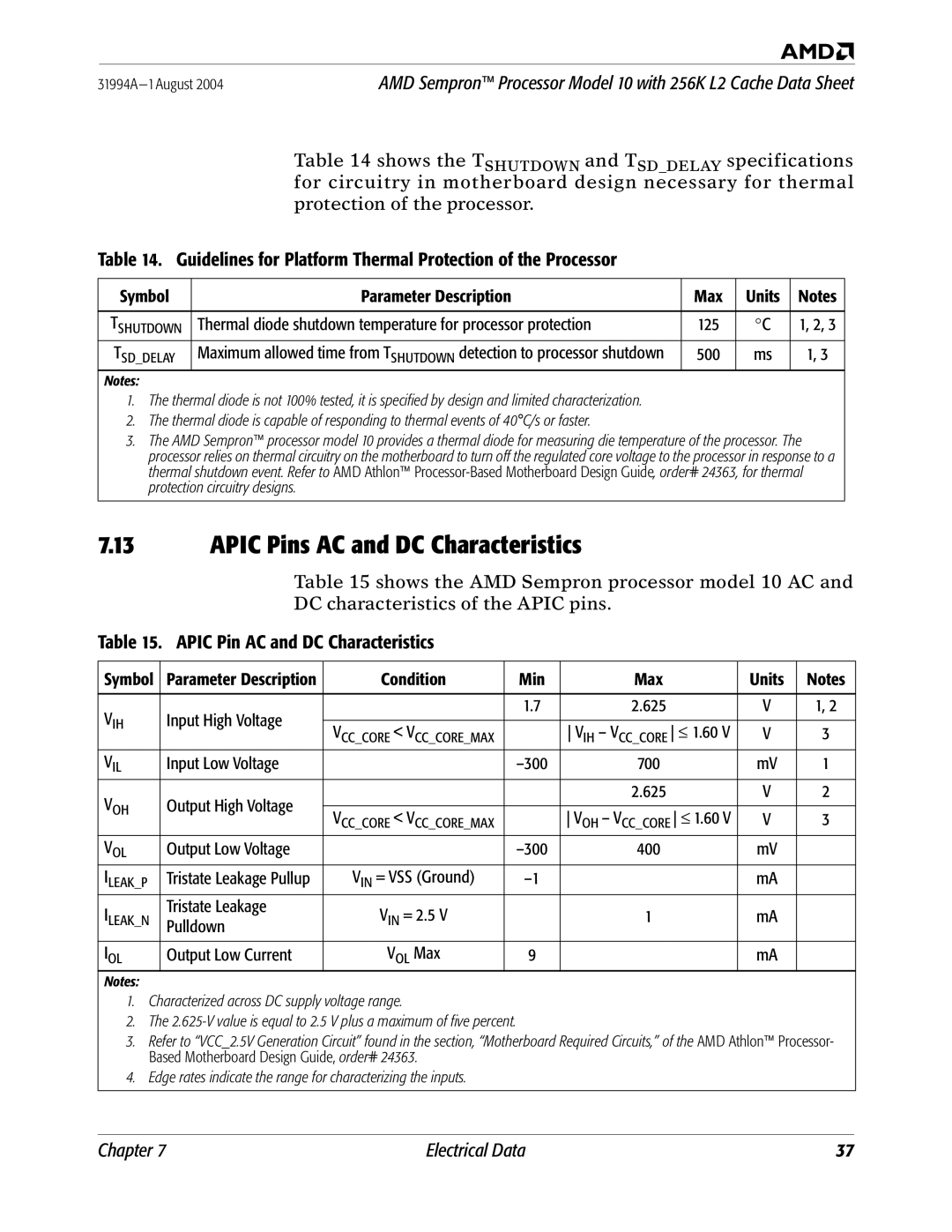
Table 14 shows the TSHUTDOWN and TSD_DELAY specifications for circuitry in motherboard design necessary for thermal
protection of the processor.
Table 14. Guidelines for Platform Thermal Protection of the Processor
Symbol | Parameter Description | Max | Units | Notes |
|
|
|
|
|
TSHUTDOWN | Thermal diode shutdown temperature for processor protection | 125 | °C | 1, 2, 3 |
TSD_DELAY | Maximum allowed time from TSHUTDOWN detection to processor shutdown | 500 | ms | 1, 3 |
Notes:
1.The thermal diode is not 100% tested, it is specified by design and limited characterization.
2.The thermal diode is capable of responding to thermal events of 40°C/s or faster.
3.The AMD Sempron™ processor model 10 provides a thermal diode for measuring die temperature of the processor. The processor relies on thermal circuitry on the motherboard to turn off the regulated core voltage to the processor in response to a thermal shutdown event. Refer to AMD Athlon™
7.13APIC Pins AC and DC Characteristics
Table 15 shows the AMD Sempron processor model 10 AC and
DC characteristics of the APIC pins.
Table 15. APIC Pin AC and DC Characteristics
Symbol | Parameter Description | Condition | Min | Max | Units | Notes |
|
|
|
|
|
|
|
VIH | Input High Voltage |
| 1.7 | 2.625 | V | 1, 2 |
|
|
|
|
| ||
VCC_CORE < VCC_CORE_MAX |
| VIH – VCC_CORE ≤ 1.60 V | V | 3 | ||
|
|
| ||||
VIL | Input Low Voltage |
| 700 | mV | 1 | |
VOH | Output High Voltage |
|
| 2.625 | V | 2 |
|
|
|
|
| ||
VCC_CORE < VCC_CORE_MAX |
| VOH – VCC_CORE ≤ 1.60 V | V | 3 | ||
|
|
| ||||
VOL | Output Low Voltage |
| 400 | mV |
| |
ILEAK_P | Tristate Leakage Pullup | VIN = VSS (Ground) |
| mA |
| |
ILEAK_N | Tristate Leakage | VIN = 2.5 V |
| 1 | mA |
|
Pulldown |
|
| ||||
|
|
|
|
|
| |
|
|
|
|
|
|
|
IOL | Output Low Current | VOL Max | 9 |
| mA |
|
Notes:
1. Characterized across DC supply voltage range.
2. The
3. Refer to “VCC_2.5V Generation Circuit” found in the section, “Motherboard Required Circuits,” of the AMD Athlon™ Processor- Based Motherboard Design Guide, order# 24363.
4. Edge rates indicate the range for characterizing the inputs.
Chapter 7 | Electrical Data | 37 |
