Preliminary Information
26237C | AMD Athlon™ XP Processor Model 10 Data Sheet |
9 Signal and Power-Up Requirements
The AMD Athlon™ XP processor model 10 is designed to provide functional operation if the voltage and temperature parameters are within the limits of normal operating ranges.
9.1Power-Up Requirements
Signal Sequence and Timing Description
3.3 V Supply
VCCA (2.5 V)
(for PLL)
VCC_CORE
RESET#
NB_RESET#
PWROK
FID[3:0]
System Clock
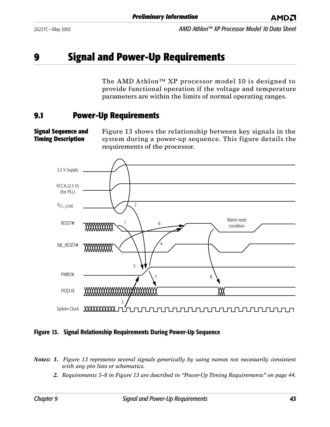
Figure 13 shows the relationship between key signals in the system during a power-up sequence. This figure details the requirements of the processor.
2 |
|
|
|
|
|
|
|
|
|
|
|
|
|
|
|
1 |
|
| 6 |
|
|
|
|
|
|
| Warm reset |
| |||
|
|
|
|
|
|
|
|
| condition | ||||||
|
|
|
|
|
|
|
|
|
|
| |||||
|
|
|
|
|
|
|
|
|
|
|
|
|
|
|
|
|
|
| 4 |
|
|
|
|
|
|
|
|
|
|
|
|
|
|
|
|
|
|
|
|
|
|
|
|
|
|
| |
|
|
|
|
|
|
|
|
|
|
|
|
|
|
|
|
5 |
|
|
|
|
|
|
|
|
|
|
|
|
|
|
|
|
|
|
|
| 8 |
|
|
|
|
|
|
| |||
7 |
|
|
|
|
|
|
|
|
|
| |||||
|
|
|
|
|
|
|
|
|
|
|
|
|
|
|
|
|
|
|
|
|
|
|
|
|
|
|
|
|
|
|
|
3
Figure 13. Signal Relationship Requirements During Power-Up Sequence
Notes: 1. Figure 13 represents several signals generically by using names not necessarily consistent with any pin lists or schematics.
2.Requirements
Chapter 9 | Signal and | 43 |