Preliminary Information
26237C | AMD Athlon™ XP Processor Model 10 Data Sheet |
8.12Thermal Diode Characteristics
| The AMD Athlon XP processor model 10 provides a diode that | ||||||||
| can be used in conjunction with an external temperature sensor | ||||||||
| to determine the die temperature of the processor. The diode | ||||||||
| anode (THERMDA) and cathode (THERMDC) are available as | ||||||||
| pins on the processor, as described in “THERMDA and | ||||||||
| THERMDC Pins” on page 77. |
|
|
|
|
| |||
| For information about thermal design for the AMD Athlon XP | ||||||||
| processor model 10, including layout and airflow | ||||||||
| considerations, see the AMD Processor Thermal, Mechanical, and | ||||||||
| Chassis Cooling Design Guide, order# 23794, and the cooling | ||||||||
| guidelines on http://www.amd.com. |
|
|
|
| ||||
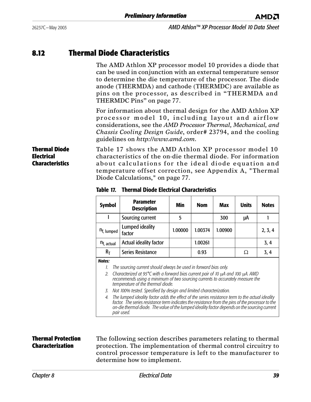
Thermal Diode | Table 17 shows the AMD Athlon XP processor model 10 | ||||||||
Electrical | characteristics of the | ||||||||
Characteristics | about calculations for the ideal diode equation and | ||||||||
| temperature offset correction, see Appendix A, "Thermal | ||||||||
| Diode Calculations," on page 77. |
|
|
|
|
| |||
| Table 17. Thermal Diode Electrical Characteristics |
|
|
| |||||
|
|
|
|
|
|
|
|
|
|
| Symbol | Parameter | Min | Nom | Max | Units |
| Notes | |
| Description |
| |||||||
|
|
|
|
|
|
|
|
| |
|
|
|
|
|
|
|
|
|
|
|
| I | Sourcing current | 5 |
| 300 | µA |
| 1 |
|
|
|
|
|
|
|
|
|
|
| n | f, lumped | Lumped ideality | 1.00000 | 1.00374 | 1.00900 |
|
| 2, 3, 4 |
| factor |
|
| ||||||
|
|
|
|
|
|
|
| ||
|
|
|
|
|
|
|
|
| |
| nf, actual | Actual ideality factor |
| 1.00261 |
|
|
| 3, 4 | |
|
| RT | Series Resistance |
| 0.93 |
| Ω |
| 3, 4 |
| Notes: |
|
|
|
|
|
|
| |
|
| 1. The sourcing current should always be used in forward bias only. |
|
|
| ||||
|
| 2. Characterized at 95°C with a forward bias current pair of 10 ∝A and 100 ∝A. AMD |
| ||||||
|
| recommends using a minimum of two sourcing currents to accurately measure the |
| ||||||
|
| temperature of the thermal diode. |
|
|
|
|
| ||
|
| 3. Not 100% tested. Specified by design and limited characterization. |
|
|
| ||||
|
| 4. The lumped ideality factor adds the effect of the series resistance term to the actual ideality | |||||||
|
| factor. The series resistance term indicates the resistance from the pins of the processor to the | |||||||
|
| ||||||||
|
| pair used. |
|
|
|
|
|
| |
|
|
|
|
|
|
|
|
|
|
Thermal Protection The following section describes parameters relating to thermal
Characterization protection. The implementation of thermal control circuitry to control processor temperature is left to the manufacturer to determine how to implement.
Chapter 8 | Electrical Data | 39 |
