Appendix
9.0Appendix
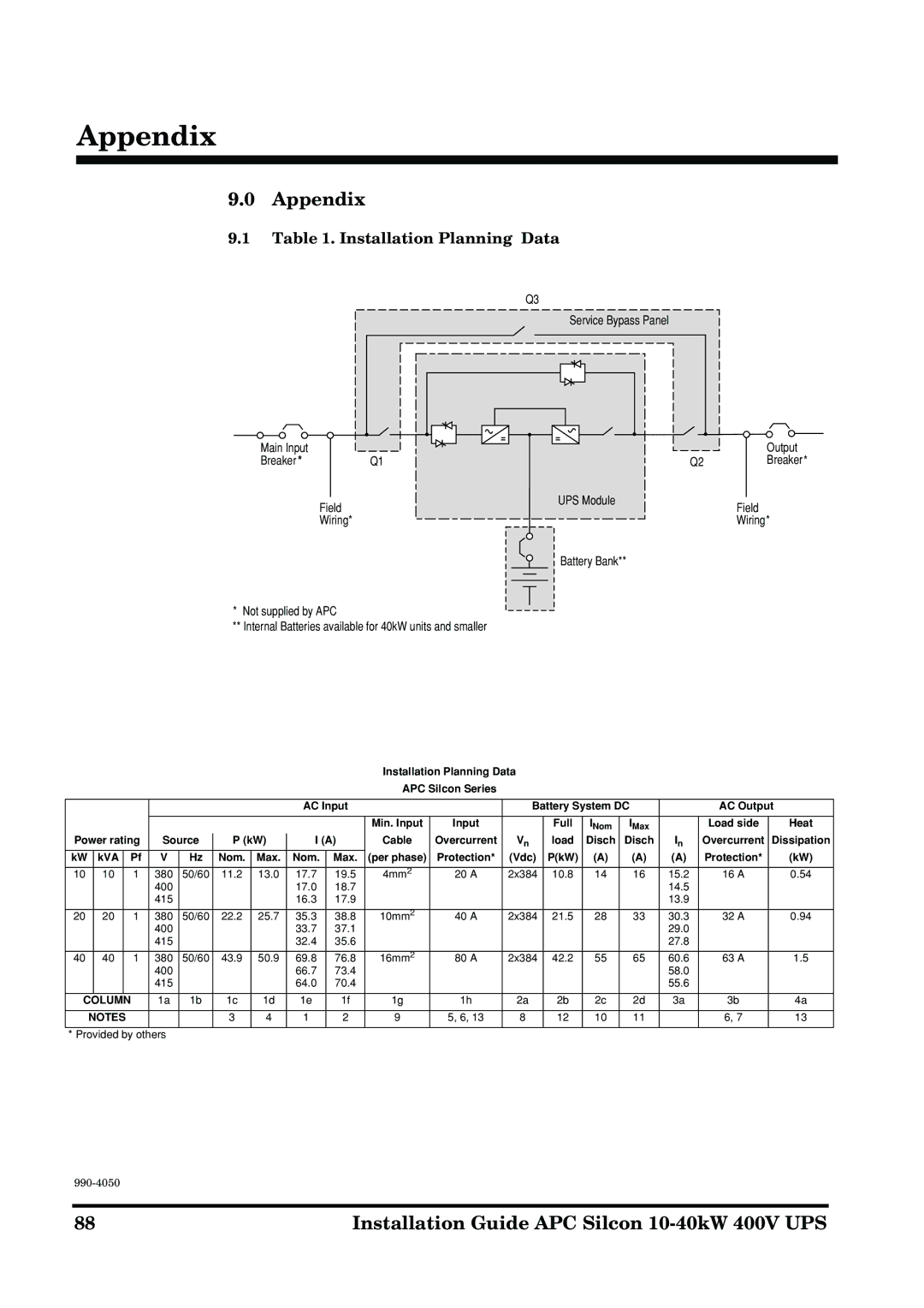
9.1Table 1. Installation Planning Data
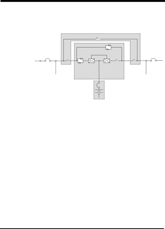
Q3
Service Bypass Panel
Main Input |
|
|
Breaker * |
| Q1 |
| Field | UPS Module |
|
| |
| Wiring* |
|
Output
Q2Breaker*
Field
Wiring*
*Not supplied by APC
**Internal Batteries available for 40kW units and smaller
Battery Bank**
Installation Planning Data
APC Silcon Series
|
|
|
|
|
|
|
|
| AC Input |
|
| Battery System DC |
| AC Output | |||||
|
|
|
|
|
|
|
|
|
|
|
|
|
|
|
|
|
|
|
|
|
|
|
|
|
|
|
|
|
|
| Min. Input | Input |
| Full | INom | IMax |
| Load side | Heat |
Power rating | Source | P (kW) | I (A) | Cable | Overcurrent | Vn | load | Disch | Disch | In | Overcurrent | Dissipation | |||||||
kW |
| kVA |
| Pf | V | Hz | Nom. | Max. | Nom. | Max. | (per phase) | Protection* | (Vdc) | P(kW) | (A) | (A) | (A) | Protection* | (kW) |
|
|
|
|
|
|
|
|
|
|
|
|
|
|
|
|
|
|
|
|
10 |
| 10 |
| 1 | 380 | 50/60 | 11.2 | 13.0 | 17.7 | 19.5 | 4mm2 | 20 A | 2x384 | 10.8 | 14 | 16 | 15.2 | 16 A | 0.54 |
|
|
|
|
| 400 |
|
|
| 17.0 | 18.7 |
|
|
|
|
|
| 14.5 |
|
|
|
|
|
|
| 415 |
|
|
| 16.3 | 17.9 |
|
|
|
|
|
| 13.9 |
|
|
|
|
|
|
|
|
|
|
|
|
|
|
|
|
|
|
|
|
|
|
20 |
| 20 |
| 1 | 380 | 50/60 | 22.2 | 25.7 | 35.3 | 38.8 | 10mm2 | 40 A | 2x384 | 21.5 | 28 | 33 | 30.3 | 32 A | 0.94 |
|
|
|
|
| 400 |
|
|
| 33.7 | 37.1 |
|
|
|
|
|
| 29.0 |
|
|
|
|
|
|
| 415 |
|
|
| 32.4 | 35.6 |
|
|
|
|
|
| 27.8 |
|
|
|
|
|
|
|
|
|
|
|
|
|
|
|
|
|
|
|
|
|
|
40 |
| 40 |
| 1 | 380 | 50/60 | 43.9 | 50.9 | 69.8 | 76.8 | 16mm2 | 80 A | 2x384 | 42.2 | 55 | 65 | 60.6 | 63 A | 1.5 |
|
|
|
|
| 400 |
|
|
| 66.7 | 73.4 |
|
|
|
|
|
| 58.0 |
|
|
|
|
|
|
| 415 |
|
|
| 64.0 | 70.4 |
|
|
|
|
|
| 55.6 |
|
|
|
|
|
|
|
|
|
|
|
|
|
|
|
|
|
|
|
| ||
| COLUMN |
| 1a | 1b | 1c | 1d | 1e | 1f | 1g | 1h | 2a | 2b | 2c | 2d | 3a | 3b | 4a | ||
|
|
|
|
|
|
|
|
|
|
|
|
|
|
|
|
|
| ||
| NOTES |
|
|
| 3 | 4 | 1 | 2 | 9 | 5, 6, 13 | 8 | 12 | 10 | 11 |
| 6, 7 | 13 | ||
|
|
|
|
|
|
|
|
|
|
|
|
|
|
|
| ||||
* Provided by others |
|
|
|
|
|
|
|
|
|
|
|
|
|
| |||||
88 | Installation Guide APC Silcon |